Configure Flash
The Configure Flash panel allows the properties of the flash device and its connection to the XJLink to be defined.
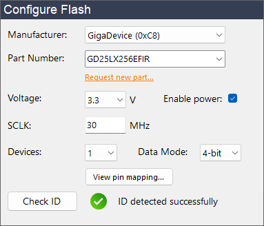
The following information is required:
- Manufacturer
-
This field allows selection of the device manufacturer and shows both name and ID for easy reference. This is an optional setting which filters the options shown in the Part Number drop-down.
NB: XJExpress supports some parts from manufacturers other than those shown in this drop-down. If you are using one of those devices, leave the drop-down showing and enter the part number below.
- Part Number
-
The part number of the flash device. The selection will be filtered as text is entered.
NB: If your part number is not listed, you can click Request new part... to send XJTAG a request for XJExpress to support your device in the future.
- Voltage
- The voltage used to read and write to pins on the device or when powering the device from the XJLink.
- Enable power
- Whether to power the flash device from the XJLink while running flash operations. This will use the selected voltage.
- SCLK
-
The maximum frequency that XJExpress should drive SCLK at. Valid values are: 0.01 MHz to 30 MHz (in steps of 0.01 MHz). If you encounter signal integrity issues, this may need to be reduced.
NB: To optimise signal integrity, we recommend using the provided XJA-0030 Splitter Board.
- Devices
-
XJExpress is capable of parallel programming up to two SPI flash devices from a single XJLink. Select the number of devices you want to program here. Click the View pin mapping... button to see the full pin-out for the chosen setting.
NB: When programming two devices simultaneously 8-bit Data Mode is unavailable.
- Data Mode
-
This defines the maximum number of pins that will be used by the SPI interface to the flash device:
- 1-bit mode supports Single SPI
- 2-bit mode supports Single SPI and Dual SPI
- 4-bit mode supports Single SPI, Dual SPI and Quad SPI (QSPI)
- 8-bit mode supports Single SPI, Dual SPI, Quad SPI (QSPI) and Octal SPI
The Data Mode sets the maximum, however the actual number of pins used is also dependant on the interface supported by the device. In some cases, a device may support different interfaces for read and write operations, e.g. QSPI reads but only Single SPI writes. XJExpress will maximise the width of the interface at all times, within the limitations of the selected data mode and SPI mode supported by the device. To see the full pin-outs of the XJLink and XJA-0030 Splitter Board (which depend on the selected data mode) click the View pin mapping... button.
Once the above information has been provided, XJExpress can verify the connection to the flash device. Click Check ID to check that the expected manufacturer and device IDs are read from the connected device.