
Configure Programming Files
The Configure Programming Files panel allows you to specify the files that will be written to the flash device.
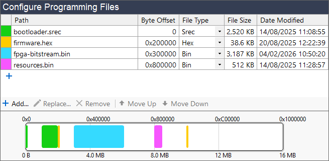
The following formats are supported by XJExpress for programming files:
- Binary (*.bin, *.rpd)
- AMD/Xilinx Bit File (*.bit)
- Intel Hex (*.hex, *.mcs)
- Motorola S-record (*.srec, *.sre)
For formats that specify address ranges, XJExpress will only program the specified addresses.
Adding and removing files
A file can be added by clicking one of the  Add... buttons to open a file browser, allowing you to navigate to the desired file and select it. You can also add a file by dragging and dropping it from Explorer.
A file in the list can be swapped with a different one by selecting it in the list and clicking  Replace... or by editing the file path directly.
You can remove a file from the list by selecting it and clicking  Remove or pressing Delete.
File paths are shown relative to the directory containing the XJExpress project (where possible).
If the file extension is recognised, the file format to use when parsing it will be set automatically, but this can be manually changed using the File Type dropdown.
NB: The file size displayed is the size of the file on disk.
Configuring programming
The order in which the files will be programmed can be changed by selecting a file and using the  Move Up and
  Move Down buttons.
A byte offset can be provided for each file to change the address within the device it will be written to. The byte offset can be given in hexadecimal, decimal or binary. For Motorola S-record and Intel Hex files, byte offsets can be negative and will be applied to the addresses contained within the file. If the address ranges of your files overlap, a warning will be displayed to let you know.
Memory visualiser
The memory visualiser graphic is a handy visual aid when configuring programming files. The data from all files in the project is displayed in the position it will appear in the address range of the target flash. The visualiser will reflect the byte offsets configured in the table above and indicate when blocks of data overlap or overflow. Mouse over a block of data in the memory visualiser to see a tooltip containing the exact address range and an explanation of any errors.
After configuring the programming files, you can setup the Workflow to control the exact steps taken when programming.