Adding manual logic devices
When we first ran the Connection Test we had to tell it to ignore the output from U9.7 which was driving and could not be disabled. Better would be to be able to tell it about the functionality of U9 so that it can test it rather than ignore it. U9 actually has two logic gates inside it but it is possible to set up only one of them. The logic gate outputting on U9.7 is driven via another logic device, inverter U10, which we will also add.
- Click the
 Connections screen button under the Setup header, then go to the Manual Devices tab.
 - Click on the
 Add button in the toolbar at the bottom of the screen.
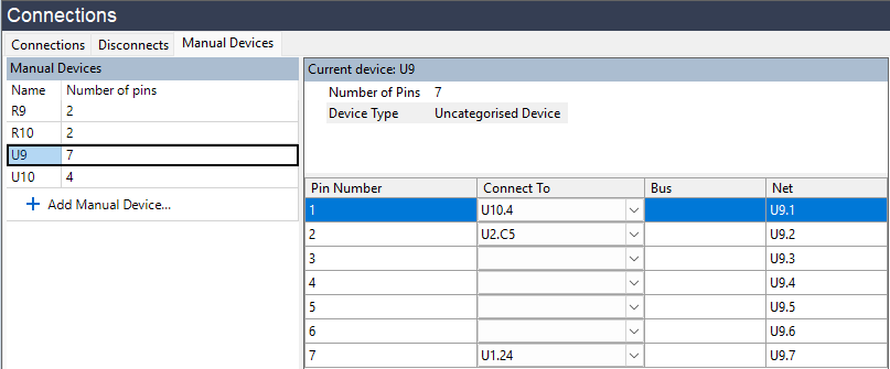
 - Set the Device Name to U9, and the number of pins to 7.
- In the Connect To column, type U2.C5 next to pin 2 and U1.24 next to pin 7. Leave the other connections blank - we only need to specify connections for the pins where we want to read or write. There will need to be another connection to pin 1 but U10 has not yet been created.
- Click the
 Apply button at the bottom of the panel
 - Click again on the Add button in the toolbar at the bottom of the screen.
- Set the Device Name to U10, and the number of pins to 4.
- In the Connect To column, type U2.C6 next to pin 2 and U9.1 next to pin 4.
- Click the Apply button at the bottom of the panel
- If you switch back to look at the U9 manual device you will see that adding the connection to it from U10.4 means it now shows an entry for pin 1, pointing back to U10.4.
We will now categorise these devices as logic.
- Click the
 Categorise devices screen button under the Setup header.
 - Expand the Suggested Devices(2) header in the Uncategorised Devices list.
- Categorise U9 by dragging it onto the Logic category in the Assign As panel.
- Click the
 Create Definition... button in the Assign Device as Logic dialog.
 - Set the Name of the new definition to be U9A
- Click OK to close the dialog.
- Now drag U10 across to the Logic category in the Assign As panel.
- This time pick the first item in the dropdown list with the name 741G04. It will have a footprint of SOT23-5, and will use pins 2 and 4, which matches U10 on the XJDemo board.
- Click OK to close the dialog.
We have now told XJDeveloper that U9 and U10 are logic, and for U10 we have set up the device from the logic library. For U9 we have not yet given any details of the device, and so we need to provide a truthtable.
- Click the
 Logic Files screen button under the Setup header.
 - Select the U9A definition from the list on the left of the screen.
- Click the Add Truth Table... button under Pin-out Details.
- Select Use Built-in Truth Table and select a NOR table with 2 inputs.
- Click OK to close the dialog.
- A truthtable will have been added in the Pin-out Details. Set the in-1 and in-2 columns to be 1 and 2, and the out column to be 7.
- Click the
 Save button at the top of the Logic Files screen.
 - Click
 Save at the top of XJDeveloper to save the project.
Now we have specified the information about the logic in the circuit, we no longer need the constant pin on the logic output.
- Click the
 Constant Pins screen button under the Setup header
 - Select the row for pin U1.24, and click the
 Remove button on the toolbar at the bottom.
Finally, we will run the Connection Test to see that it still passes.
- Click the
 Run Tests screen button under the Run and Deploy header.
 - Click the
 Run button to run the Connection Test, saving when prompted.
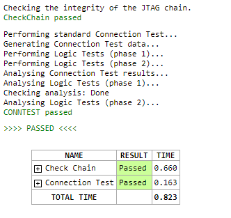
From the extra output messages that Connection Test generates, we can see that it has tested the logic around IC9.
The next step will cover functionally testing a manually created device, using an XJEase file from the library.
XJTAG v4.3.0