Importing BOM Data
When developing a boundary scan test, the circuit’s components will need to be categorised so that the software knows how to treat them. To simplify that process, XJDeveloper will make intelligent suggestions based on its knowledge of the circuit. Adding a BOM to the project gives XJDeveloper additional information that allows it to make those suggestions as accurately as possible.
It is possible to extract BOM information from up to 3 different sources: from an external BOM, from the netlist, or from a schematic. The user can select the best source for each piece of information, and it may be beneficial to use a mix of sources to obtain the optimum set of data.
It is normally best to add data from an external BOM file first because that is most likely to capture the latest build standard. Then, inspect the data available from the schematic and add any additional information from that. Finally, pick any remaining data from the netlist to provide content for any fields that are still missing or inadequately populated.
These three methods are described in the following sections.
Importing an External BOM File
A BOM file can be imported by clicking the Import BOM... button in the Add Board dialog box (after selecting a netlist):
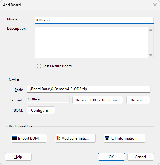
Figure 7: Using the Add Board Dialog Box to import a BOM File
In the resulting Select File dialog (Figure 8), browse to the file's location. XJDeveloper will automatically detect the appropriate format for many common file types such as CSV or Excel, but if it is not recognized, the user will be asked to select a format as shown in Figure 8; delimited and fixed-width BOM files are supported alongside CSV and Excel formats.
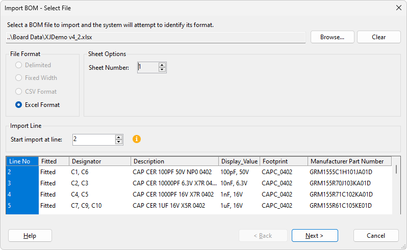
Figure 8: Importing an External BOM file
- A BOM can only be imported after the netlist has been processed because the system needs to match reference designators in the BOM to those in the netlist. The Import BOM... button will therefore be greyed-out until a netlist has been satisfactorily parsed.
Analysing BOM Data Fields
After clicking the Next button, the user will be asked to select which columns provide useful data, and to define which type of data they contain. Some columns can be ignored—for example, Quantity will not help later with device categorisation — whereas fields such as Value and Footprint may aid that process.
- Because of how XJDeveloper will use the chosen BOM fields later during device categorisation, it is important to provide it with as much relevant information as possible about components in the circuit. For example, the part number helps when assigning device models; and resistor values help when determining resistor functions and recognising power rails. It’s therefore beneficial to invest time to fully understand XJDeveloper’s different data types and how they are used (see below), and not to rush through this step. Give careful consideration to what BOM information is available from different sources and ensure column assignments are performed correctly.
Figure 9 shows how to select the desired BOM columns by assigning a data type to each column of interest from the dropdown menu. By default, XJDeveloper will have automatically assigned one column to the Reference type and will have set the others to None; BOM columns to be ignored should be left at None.
If XJDeveloper fails to identify any column as a reference column, it is likely that the netlist or BOM has not been correctly imported, or that the netlist part of the ODB++ structure is missing. If an attempt is made to move to the next step without a reference column, an error message will be displayed.
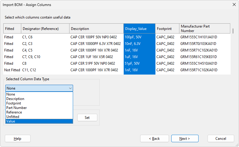
Figure 9: Setting BOM Data Column Types
- Data can be sorted by clicking the column headings
BOM data types
XJDeveloper’s different BOM data types are as follows, although not all need to be used:
- None: used for columns to be ignored (such as Quantity). This is the default value for all columns other than the device reference.
- Description: a column that contains descriptive information about each device (for example: "RES SMD 4K7 1% 0.1W 0402" or "IC EEPROM 2kbit I2C 1MHz SOT23-5"). If this field also includes component values and part numbers, XJDeveloper will attempt to extract that information if the separate Value and Part Number fields are empty.
- Footprint: footprint information is used when suggesting which device model to use for logic devices (a device will have a different model for alternative footprints).
- Part Number: for the manufacturer's part number. The software will use this when suggesting which library model file to allocate to a device. If the BOM's part number field contains company part numbers instead of the manufacturer's, a mapping file should also be provided as described in the section on Translating Company Part Numbers.
- Reference: used for reference designators (R1, C2 etc.). The software uses this information to reference each device in the circuit, and it is therefore mandatory to have a reference column defined. The system will automatically assign one column as Reference based on an analysis of its contents.
If a BOM groups identical components into single rows, those devices will subsequently be displayed on separate lines. For example, if a BOM has three 10 nF capacitors on the same row with "C1, C2, C3", "C1-C3", "C1-3", or similar in the Reference column, their details will be extracted and each capacitor will later be shown on its own line.
XJDeveloper will use the reference field later in various ways when making suggestions for categorisation: for example, the software is configured by default so that a device with a reference starting "FB" is assumed to be a ferrite bead. That information helps when XJDeveloper examines power and ground nets: if it finds such a device connected to a supply rail, it will suggest the net connected to the other pin is also a power net. - Unfitted: for a column that identifies any devices that are not being placed during board assembly. The software can use this field when performing its intelligent analysis of the circuit – for example, if 0 Ω links have been used in the JTAG chain to allow alternative configurations, knowing which links have been omitted will enable it to correctly identify the JTAG chain. It is also used to propose any devices that should not be included in the circuit model, so it is important to use this data type when such information is available.
- Value: for columns containing component values (10R, 100nF etc.). This is used during various analyses, for example to intelligently propose categorisations for resistors as either series, pull or "other". If this column also contains part numbers, XJDeveloper will attempt to extract that information from this data type if the Part Number field is empty.
Users can also add additional custom fields if necessary. Once added, these will appear at the bottom of the menu items shown in Figure 9 above.
- If a BOM column has text that includes both the value and part number, allocating it to XJDeveloper’s Value data type will allow the software to extract part numbers as well as values from it (if allocated to the Part Number data type, XJDeveloper will be unable to extract the value information from that column). See the section on Examples of BOM Column Assignments for the best ways to allocate BOM columns.
- Part Number and Value are the two most beneficial items, so it is helpful to ensure the column or columns providing that data are as fully populated as possible.
- XJDeveloper will also use the Value, Part Number and Description fields later during device categorisation when assigning devices to the Test category. For example:
- these fields are used when attempting to match a device to a test-device file in the XJEase library.
- some XJEase models come with a set of default configuration variables (for example, a flash memory will have details of block size, number of blocks etc.): if the part number matches that of a stored XJEase file, XJDeveloper will automatically suggest the appropriate configuration settings.
- when a new test device file is created, XJDeveloper will use the contents of the Part Number field to propose a filename and device name, and will populate the file description box with text from the Description field.
Custom Data Types
If the user wants to ensure a particular column is imported but a suitable data type is not available from the dropdown menu, it is possible to provide a custom name by selecting the column, entering a suitable name in the Define Custom Type box and clicking Set as shown in Figure 10. This can be useful when a BOM field contains additional information that the user wants to have available during the rest of the board setup: for example, a column might provide additional data that could help users assess the proposed assignments of library files to devices during device categorisation.
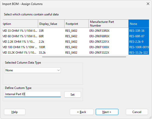
Figure 10: Using Custom Data Types
Reviewing the BOM
Once the relevant columns have been assigned, clicking the Next button will take the user to a summary of what the imported BOM will look like. Each device will have been given its own row even if they were grouped by value in the original file.
- If the Description field contains value information (for example, resistor 22K), XJDeveloper will recognize this when Next is clicked and will be able to extract that information to populate the device values. If this can be performed and a Value column has not already been allocated, a dialog box will appear before the summary is displayed, which will ask if the user wants to use the data it can extract.
The user should then review the information displayed to ensure it is as expected. Clicking Back will allow changes to be made, or selecting Finish will complete the import of BOM data, although it remains possible to edit the information later if needed.
XJTAG v4.3.0