Stage 2 – Power and pin mapping options
You will now see the Project Setup Wizard, which you can use to configure the JTAG interface on your XJLink2.
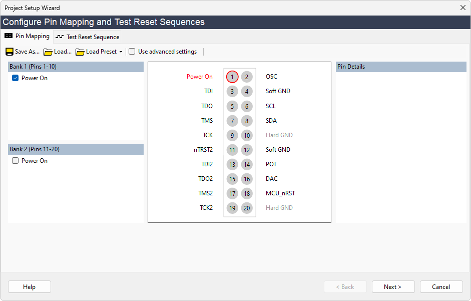
The Pin Mapping Tab will be selected. This allows you to specify how the pins on the XJLink should be used, and select whether to power the circuit through the USB connection.
The configurable pin mapping of the XJLink gives great flexibility, but for this tutorial, using the XJDemo board, you can use one of the predefined pin mapping options. The XJDemo board also needs to be powered through the USB connection. To set up this configuration:
- Connect P1 on the XJDemo board to the XJLink with the 20-way ribbon cable.
- Select XJDemo4 from the Load Preset dropdown list.

- Click Next to move to the final stage of configuration.
After clicking Next you will see a pop-up warning you that powering your circuit in this way may damage your USB interface. Because the XJDemo board is designed to use USB power, it is safe to do this:
- Click Yes to continue.
In the picture above are some pins marked as Soft Ground. This designates a pin which is driven low by the XJLink, and which is driven through a lower impedance than a normal low signal. However, it is not such a good ground connection as Pin 10 or Pin 20 (Hard Ground).
XJTAG v4.2.3
