Manually Identifying the JTAG chain
This exercise shows how to set up the JTAG chains on the XJDemo board without using the Suggest Chains... feature; it will build on a version of the completed tutorial project with the configuration for the Pin Mapping, JTAG chains and related devices removed. A copy of this project is installed as a zip file: Demo4NoJTAG.zip.
- Extract the zip file Demo4NoJTAG.zip to a new, empty directory of your choice.
- Navigate into the Board Test directory.
- Open the XJDemo Board.xjd project from the extracted files, using XJDeveloper.
In order to make sure the JTAG chains you are describing are consistent with the netlist, XJDeveloper guides you from the point you specify as TDI for each chain, through the devices that make up that JTAG chain to TDO.
On the XJDemo board P1 is the JTAG connector and, from the circuit diagram, the TDI and TDO pins can be identified. It is important to understand what is meant by TDI and TDO: TDI is the test data input to the circuit; TDO is the test data output from the circuit.
There are two JTAG chains on the XJDemo board. One of them contains the CPLD, the other contains the MCU. You will set up the CPLD's chain first:
- Click the
 JTAG Chain screen button under the Setup header.
 - Click the
 Add... button at the bottom of the Chain Setup section.
 - Set the Name of this chain to CPLD chain.
- Click the Select... button next to the TDI text box in the Add Chain dialog.
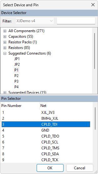
- Open the Suggested Connectors list in the Device Selector section of the Select Device and Pin dialog.
- Click on P1.
- Select pin 3 in the Pin Selector section of the Select Device and Pin dialog.
- Click OK in the Select Device and Pin dialog and click OK in the Add Chain dialog, leaving TDO blank.
- Click the
 Save button on the main XJDeveloper toolbar.
Similarly, the TDO pin can be set in this way. There is an easier way to do this though, as you will see after all the devices in this chain have been categorised.
Now that P1.3 has been defined as being TDI to this JTAG chain, XJDeveloper finds and displays all the pins attached to the same net as P1.3. These are listed under the Select Next Device header in the Selected Chain.
For this chain there are three other pins connected to the TDI connector pin, P1.3:
- R11.1 - a pull resistor.
- TP64.1 - a test point.
- U1.15 - the TDI pin for the first device in this JTAG chain.
- Double-click on U1.15 in the Select Next Device list to select this as the next pin/device in the JTAG chain.
A device in the JTAG chain can be categorised in one of three ways:
- Assign as JTAG device - This option tells the system that the device can be directly controlled during testing. In order to categorise a device as a JTAG device you will need the BSDL file which can normally be downloaded from the device manufacturer's website.
- Assign as Connect device - This option tells the system that the device connects nets on the circuit. PDD files are used to describe Connect devices such as resistors and jumpers in the JTAG chain.
- Use pin connection to another device - This option is used to describe external connections, normally a cable used to link between JTAG headers on a circuit. Using this option will add a connection on the
 Connections screen.
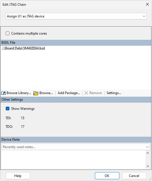
The Edit JTAG Chain dialog defaults to assigning devices with more than two pins as JTAG devices so Assign U1 as JTAG device is already selected. Now you need to select the BSDL file that will tell XJTAG how to control the pins of this device.
- Click the
 Browse... button in the Edit JTAG Chain dialog.
 - Navigate up one level in the directory structure and then go into the Board Data directory.
- Select 5M40ZE64.bsd from the files listed and then click Open.
- Click OK on the Edit JTAG Chain dialog.
You will now be prompted to ask if you want to add the selected BSDL file into the BSDL Library. Adding BSDL files to the library is very useful for when you are using other XJTAG applications. The JTAG Chain Debugger and XJAnalyser both use the BSDL Library to automatically match IDCODEs read from your JTAG chain to the BSDL files that describe the implementation of JTAG on those devices.
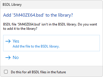
For this exercise you do not need to add the BSDL files to the library.
- Click No on the BSDL Library dialog.
- Click the Save button on the main XJDeveloper toolbar.
XJDeveloper now checks the selected BSDL file to make sure the TDI pin in the file is the same as the pin you have just selected from the Select Next Device section.
The pin number for TDO is then extracted from the BSDL file and the other pins on the TDO net are displayed in the Select Next Device section. In this instance there is only one option - R14.1, a series termination resistor.
Although R14 is not a JTAG device it is in the JTAG chain. In order to continue routing the chain through the netlist the system needs to know that R14 simply connects the net connected to pin 1 to the net connected to pin 2.
- Double-click on R14.1 from the Select Next Device section.
Because R14 is a two pin device XJDeveloper has preselected the Assign R14 as Connect device option from the dropdown list at the top of the Edit JTAG Chain dialog. The correct PDD file, resistor.pdd has also been identified so you just need to accept this suggestion.
- Click OK at the bottom of the Edit JTAG Chain dialog.
The Select Next Device section now shows the pins connected to the net on the other side of R14. There are four pins to select from.
- Click the
 Show Schematic Viewer button on the main XJDeveloper toolbar to investigate the options.
 - Search for LK1.1 using the Netlist Search on the toolbar of the Schematic Viewer window.
You can see that LK1 is a single jumper. If the jumper is fitted it would connect the TDO net from the CPLD chain to the TDI net of the MCU chain. This jumper should not be fitted on the XJDemo board you are using during this exercise.
Searching for R12.1 will show that R12 is a pull resistor ensuring the TDO net is pulled up when not driven. TP6.1 is a test point on the TDO net, so neither of these options will complete the chain to reach the TDO pin.
- Search for P1.5 using the Netlist Search on the toolbar of the Schematic Viewer window.
It is clear from the schematic this is the TDO pin on the JTAG connector for this JTAG chain and is therefore the correct pin to choose from the list. To complete the chain, P1.5 needs to be set as TDO.
- Select P1.5 and click on the Set as TDO button.
- Click the Save button on the main XJDeveloper toolbar.
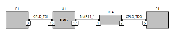
This completes the CPLD JTAG chain which is displayed as shown below.
Having completed the setup of the CPLD chain the steps now need to be repeated for the MCU chain.
- Click the Add... button at the bottom of the Chain Setup section.
- Set the Name of this chain to MCU chain.
- Click the Select... button next to the TDI text box in the Add Chain dialog.
- Open the Suggested Connectors list in the Device Selector section of the Select Device and Pin dialog.
- Click on P1.
- Select pin 13 in the Pin Selector section of the Select Device and Pin dialog.
- Click OK in the Select Device and Pin dialog and click OK in the Add Chain dialog.
- Click the Save button on the main XJDeveloper toolbar.
You will see in the Select Next Device list that the net containing the TDI pin of the MCU chain also contains a pin on LK1 which you previously saw on the TDO net of the CPLD chain. The TDI pin of the MCU is U2.H8 so that needs to be selected as the next device.
- Double-click on U2.H8 in the Select Next Device section to select this as the next pin/device in the JTAG chain.
- Click Browse... in the Edit JTAG Chain dialog.
- Select K22_121BGA.BSDL from the files listed and then click on Open.
- Click OK on the Edit JTAG Chain dialog.
- Click the No button on the BSDL Library dialog.
- Click the Save button on the main XJDeveloper toolbar.
There is another series termination resistor, R6 that needs to be categorised as a Connect Device to allow the chain to be routed back to the JTAG connector, P1.
- Double-click on R6.1 in the Select Next Device section.
- The Edit JTAG Chain dialog has identified resistor.pdd as the correct file to use. Therefore, click OK at the bottom of the dialog to accept the suggestion.
- Select P1.15 in the Select Next Device section and click the Set as TDO button.
- Click the Save button on the main XJDeveloper toolbar.
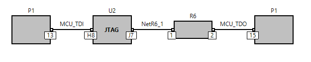
This completes the MCU JTAG chain which is displayed as shown below.
There will be an error in the Errors pane at this point, because no pin mapping has been assigned in this project.
- Click the
 Pin Mapping screen button under the Run and Deploy header.
 - In the Pin Mapping menu at the top of the screen, expand the Load Pin Mapping Preset item, and then select XJDemo4.
- Click the Save button on the main XJDeveloper toolbar.
There is also a warning in the project which can be ignored, or can be disabled as you did in the main part of the tutorial by right-clicking on the warning and selecting Hide Warning.
All the tests in this project will now run as they did at the end of the main tutorial.
See Also
XJTAG v4.2.5