Adding a Board That Forms a Test Fixture
To extend fault coverage so that a boundary scan test can fully check the board's connectors, it can be beneficial to include a PCB in the test jig that has mating connectors and a JTAG device. By joining the two boards together, the connector’s solder joints can be fully tested. Boards like the one inside the jig are referred to as "test fixture boards".
In those instances, it can be desirable for test results to report only nets that are on the board under test rather than including any on the test fixture board. Designating a board as part of a test fixture at this stage means the operator will be offered the opportunity for its nets to be omitted from XJRunner's error messages.
There are checkboxes to identify a board as part of a test fixture in the Add Boards dialog box and in the summary of board information in the Boards screen:
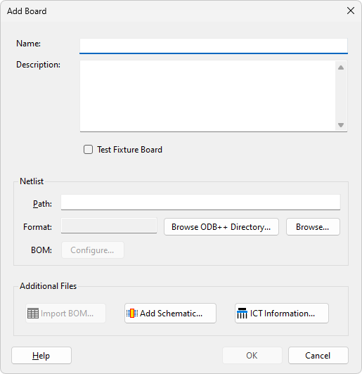
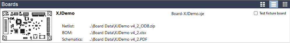
Figure 21: Designating a Test Fixture Board
XJTAG v4.3.0