Hardware Configuration
Before you can use the XJIO board to extend the testing of a UUT, you need to make sure all the required connections have been setup. These connections are both between the UUT and the XJIO board and within the XJIO board.
JTAG chain configuration
In order to use the XJIO board you need to connect the XJLink to the JTAG chains of both the XJIO board and the UUT. In this exercise we will use the ability of the XJIO board to add the JTAG devices of the UUT onto the end of its JTAG chain before routing the final TDO signal back to the XJLink.
- Connect the XJLink to CN1 on the XJIO board using a cable with standard 20-way 0.1" IDC connectors.
- Connect the external JTAG connector on the XJIO board (CN2) to the JTAG connector on the XJDemo board (P1), using a cable with standard 20-way 0.1" IDC connectors.
Once the XJLink is connected you need to make sure the configuration jumpers are correctly placed to route the JTAG signals to the correct nets on the XJIO board.
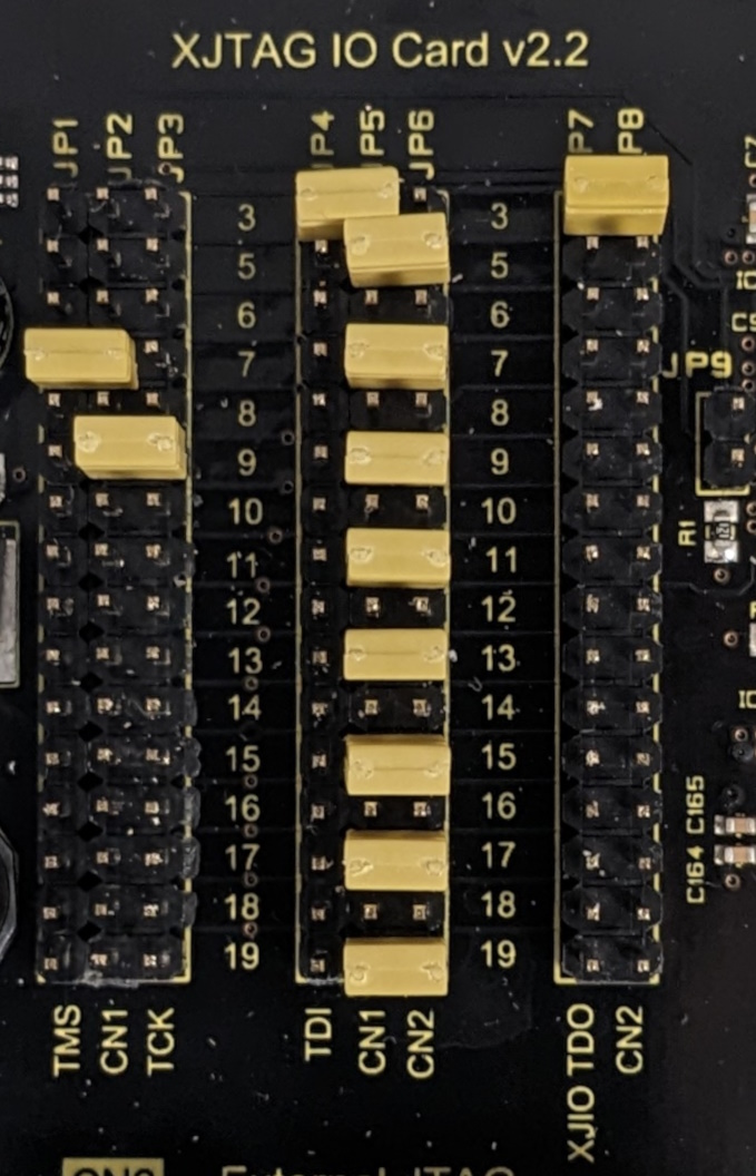
First we will route the signals on the XJIO board from the required pins on CN1 to the board's JTAG chain:
- XJIO TDI - place a link between JP4.3 and JP5.3.
- XJIO TMS - place a link between JP1.7 and JP2.7.
- XJIO TCK - place a link between JP3.9 and JP2.9.
Next, we will add the CPLD JTAG chain to the end of the JTAG chain on the XJIO board.
To route the JTAG signals for the required connections to and from the CPLD on XJDemo v4 (this chain is added to the end of JTAG chain on the XJIO board):
- CPLD TDI (TDO from the XJIO board) - place a link between JP7.3 and JP8.3.
- CPLD TMS (connected to the TMS net for the XJIO board) - place a link between JP5.7 and JP6.7.
- CPLD TCK (connected to the TCK net for the XJIO board) - place a link between JP5.9 and JP6.9.
- CPLD TDO (routed through the XJIO board back to the XJLink) - place a link between JP5.5 and JP6.5.
Finally, the XJDemo v4 board has two chains. The second chain (to the MCU) we will just route through the XJIO board to the XJLink2:
- MCU TDI - place a link between JP5.13 and JP6.13.
- MCU TMS - place a link between JP5.17 and JP6.17.
- MCU TCK - place a link between JP5.19 and JP6.19.
- MCU TDO - place a link between JP5.15 and JP6.15.
- MCU nTRST - place a link between JP5.11 and JP6.11.
You have now completed all of the hardware configuration required to create a complete JTAG chain.
Checking the JTAG chain
The easiest way to check that your hardware setup is correct is to use the JTAG Chain Debugger, launched from the Windows Start Menu under XJTAG -> Utilities.
After launching the JTAG chain debugger you will first need to setup the pin mapping that should be used.
- Select XJDemo4 from the
 Load Preset dropdown list.
The XJIO board is designed to be powered using an external supply; however for this exercise you are going to use the ability of the XJLink to apply a small amount of power onto pin 1 to power the XJIO board.
As the XJIO board has a soft start function you need to configure a delay into the system to allow the time for it to power up after the XJLink power is turned on but before testing starts. This will be configured in a Test Reset Sequence.
- In the JTAG chain debugger click on the Test Reset Sequence tab.
- Click Add....
- Name the sequence Power-up delay.
- Don't select any of the JTAG pins and click OK.
- Click Add Step, select Sleep and set a delay of 200 ms.
- Click Add Step again and select Pulse nTRST.
- Drag the TMS Reset from step 1 to step 3.
In normal operation the XJIO board should be powered from an external supply. The power that can be supplied by the XJLink will quickly be exceeded if a large number of IOs are connected between an XJIO board and a UUT. If you are powering the XJIO board using an external supply, you should disable the XJLink supply.
Everything is now configured and when you run Check Chain you should see the following:
Starting Check Chain...

16 devices found
ID codes read:
  0x11804043
  0x11804043
  0x11804043
  0x11804043
  0x11804043
  0x11804043
  0x11804043
  0x11804043
  0x11804043
  0x11804043
  0x11804043
  0x11804043
  0x11804043
  0x11804043
  0x020A50DD
  0x4BA00477

Chain intact

Instruction Register length: 126

Device 1: Correct Boundary Scan Register length: 68
Device 2: Correct Boundary Scan Register length: 68
Device 3: Correct Boundary Scan Register length: 68
Device 4: Correct Boundary Scan Register length: 68
Device 5: Correct Boundary Scan Register length: 68
Device 6: Correct Boundary Scan Register length: 68
Device 7: Correct Boundary Scan Register length: 68
Device 8: Correct Boundary Scan Register length: 68
Device 9: Correct Boundary Scan Register length: 68
Device 10: Correct Boundary Scan Register length: 68
Device 11: Correct Boundary Scan Register length: 68
Device 12: Correct Boundary Scan Register length: 68
Device 13: Correct Boundary Scan Register length: 68
Device 14: Correct Boundary Scan Register length: 68
Device 15: Correct Boundary Scan Register length: 240
Device 16: Correct Boundary Scan Register length: 134

Check Chain complete
Connecting the UUT to the XJIO board I/O pins
- Use a cable with standard 20-way IDC connectors to link the 20-way connector X12 on the XJIO board to the digital IO connector on the XJDemo board (P3). X12.1 on the XJIO board should be connected to P3.1 on the XJDemo board.
XJTAG v4.3.0