Defining JTAG Terminations
Because JTAG signals run at high speed over relatively long distances, they require the terminations described below in order to achieve good signal integrity and a reliable connection:
- TCK: RC load termination near the final device
- TDO: series termination and a pull-up
- TDI: pull-up
- TMS: pull-up
- nTRST: pull-down and HF filtering
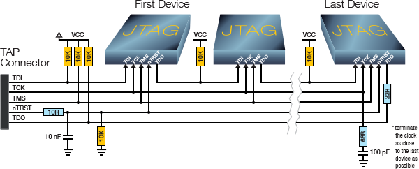
Figure 4: The ideal set of JTAG terminations
- Give particular attention to the board’s terminations: while pull-ups and pull-downs can be inserted into the cable if forgotten on the board, placing terminating components in the correct position without PCB pads is far more troublesome!'
TCK Termination
Terminate the clock line with an RC series termination to match the characteristic impedance of the cable and PCB tracks. Values of 68 Ω and 100 pF are typically used as shown in Figure 4 and will adequately match most cables; they should be placed as close as possible to the pin of the last device in each JTAG chain.
- To avoid introducing unique components to the design, these values can be altered as they are not normally particularly sensitive. Resistances from 50 Ω to 120 Ω are acceptable, as are capacitances up to 1 nF. Removing the capacitor altogether and just teriminating with a 120 Ω load can work satisfactorily in some situations, but it is strongly recommended that pads for the capacitor are kept on the board and shorted with a 0 Ω link in case improved performance is needed later.
TDO Termination
Source terminate the TDO line with a small series resistor on the board near the last device of each JTAG chain as shown in Figure 4; its value is typically 22 Ω.
nTRST and Other Asynchronous Inputs
To prevent noise picked up by the cable causing spurious resets, it is recommended that a small RC filter be placed close to the connector as shown in Figure 4 on nTRST and any other asynchronous inputs. Values of 10 Ω and 10 nF are recommended, which will not slow the edge of the signal enough to cause problems.
- If the user is unable to implement this RC filter, omitting the series resistor and just allowing the capacitor to filter against the cable resistance can work on some test fixtures.
Pull-ups / Pull-downs
The other TAP lines should have 10 kΩ pull-ups and -downs as shown in Figure 4. This ensures they are kept in the required state when the JTAG interface is not in use. Resistances between 1 kΩ and 10 kΩ are acceptable.
- TMS: the pull-up on TMS protects the TAP controller’s state machine from the effect of any glitches on TCK: by ensuring it is high, any spurious clock transitions that might be caused by interference cannot take the state machine out of its reset state. It therefore protects against unitended instructions being executed.
- TDI: Keeping the TDI line high with a pull-up ensures that, if cross-talk did succeed in clocking something into the instruction register, it will only be a series of ‘1’s, which is the instruction to put the device into bypass. This helps to protect it from accidently entering boundary scan mode during normal operation.
- TDO: although TDO is considered an output from the JTAG device, the specification requires it to be tri-state except when data is being scanned. This pull-up is therefore needed to remove the risk of a floating input.
- As TDO provides the input to the next JTAG in the chain, the benefit of pulling this line is the same as for TDI above.
- nTRST requires a pull-down to ensure the JTAG state machine of any devices supporting nTRST are held in reset when not in use.
- Some manufacturers recommend placing a pull up on nTRST, but this is because their JTAG controllers do not drive that signal. A pull up is contrary to the JTAG specification and should not be used with XJTAG’s controllers.
XJTAG v4.3.0