XJLink Programmable I/O
XJTAG's XJLink controllers have connector pins with configurable functionality, which is set as part of your XJTAG project. The XJLink2 series of controllers have 18 configurable pins out of a total 20 pins on the XJLink2 connector. The XJLink-PF20 has 20 configurable pins out of the 40 pins across its 2 connectors, and the XJLink-PF40 has 40 configurable pins out of the 80 pins across its 4 connectors.
The pins that cannot be configured, which are pins 10 and 20 on an XJLink2 and all even-numbered pins on an XJLink-PFxx controller, provide Ground connections between the XJLink and the UUT. As well as linking the voltage levels between the test controller and the UUT, ground pins can be used to improve signal integrity on high-speed signals elsewhere in the connection.
The most obvious use for the configurable pins is for TAP connections to JTAG ports on the UUT. However, any pins that are not directly required to communicate with a JTAG chain can be used as PIO.
When an XJLink pin is configured as PIO it can be used as part of a Test Reset Sequence or be controlled from XJEase as part of a test or programming function. In this exercise you will use PIO pins to control the I2C bus connected to the ADC and EEPROM on the XJDemo board.
All of the configurable pins on an XJLink can also be used to take voltage and frequency measurements. In order to do this, pins used for taking such measurements must be configured as PIO. This allows you to name the pins to make their purpose clear for other engineers who may need to maintain the project. This exercise will show you how to use this functionality, measuring the frequency of the oscillator (X1), and the voltage output by the potentiometer (accessed via pin P1.14) on the XJDemo board.
Configuring PIO pins
To use an XJLink pin for PIO it must first be configured on the Pin Mapping screen.
The exercise will build on a version of the completed tutorial project with the PIO pins removed from the Pin Mapping. This project is installed as a zip file: Demo4NoPIO.zip.
- Extract the zip file Demo4NoPIO.zip to a new, empty directory of your choice.
- Navigate into the Board Test directory.
- In that directory, open XJDemo board.xjd with XJDeveloper.
- Click the
 Pin Mapping screen button under the Run and Deploy header.
One difference between the project you have just opened and the project you created in the main tutorial is that this project has pin mappings for multiple XJLink types. A project like this with multiple pin mappings needs to have the pin mappings in sync with each other. To simplify this tutorial and avoid configuring items in each pin mapping the easiest thing to do at this point is to remove the pin mapping you are not using.
- In the Supported XJLink Types panel to the left of the pin mapping diagram, there will be multiple entries. For each type of XJLink which is not being used right now, select the item and then click Remove XJLink Type underneath the control. This will leave only your current XJLink type in the project.
If you wish to develop a project containing multiple pin mappings then instead of removing one pin mapping you can simply switch between them and modify both appropriately. Error messages in XJDeveloper will let you know if you have configurations in one pin mapping that do not match the other.
Having now only a single pin mapping in the project we must now configure it with some PIO pins:
If you are using an XJLink2 or PXI-XJLink2:
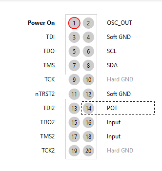
- Click on pin 2 on the connector diagram. The Pin Details panel now shows information for this pin.
- In the Pin Details panel click on the Type dropdown menu and select PIO.
If you are using an XJLink-PFxx controller:
- Select connector A on the XJLink connector map.
- Click pin 3 of the connector A diagram. The Pin Details panel now shows information for this pin.
- In the Pin Details panel click on the Type dropdown menu and select PIO.
The default PIO Name is based on the pin number. You are going to change this to give it a more descriptive name.
- Set the PIO Name for the selected pin to OSC_OUT.
If you are using an XJLink2 or PXI-XJLink2:
- Repeat the instructions above to set pin 6 to be a PIO pin named SCL.
- Repeat the instructions above to set pin 8 to be a PIO pin named SDA.
- Repeat the instructions above to set pin 14 to be a PIO pin named POT.
If you are using an XJLink-PFxx controller:
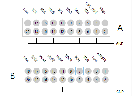
- Repeat the instructions above to set pin A.11 to be a PIO pin named SCL.
- Repeat the instructions above to set pin A.15 to be a PIO pin named SDA.
- Repeat the instructions above but this time selecting the B connector, to set pin B.7 to be a PIO pin named POT.
- Click the
 Save button on the main XJDeveloper toolbar.
This gives the pin mapping shown below:
| XJLink2 | XJLink-PFxx |
|---|---|
 |
|
Measuring frequency
The frequency measured at an XJLink pin can be read as part of an XJTAG test system or directly on the Pin Mapping screen.
- Click Live Mode in the bar below the connector diagram and select On.
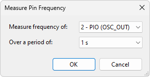
- Click Pin Frequency at the bottom of the Pin Mapping screen.
- Select the PIO (OSC_OUT) pin (pin 2 on an XJLink2 or pin A.3 on an XJLink-PFxx controller) in the Measure frequency of dropdown.
- Select 1 s in the Over a period of: dropdown.
- Click OK to accept the measurement conditions.
The measured frequency is displayed in the Pin Mapping output panel. Changing the period of the measurement will affect the accuracy of the measurement.
The oscillator on the XJDemo board needs to be enabled in order to generate its 8 MHz output. If the CPLD on the XJDemo board is not configured, a pull resistor will cause the oscillator to be disabled.
If you see a value of 0 MHz being returned please program the CPLD using the installed test project in the XJTAG shared folders and try rerunning this test.
The next part of the exercise will show you how to add frequency measurement using this PIO pin to an XJEase test function.
Most XJEase code is used to test a particular type of non-JTAG device. Such tests are written in Test Device Files and can be reused whenever that type of device is used on any board.
This test is specific to the current project, so as such it will be written in a Circuit Code File.
- Click the
 Circuit Code Files screen button under the Setup header.
 - At the top of the Circuit Code Files screen, click the
 button and select New... from the dropdown.
 - In the New Circuit Code File window enter the file name XJLinkPIO.xje and click Save.
A new Circuit Code File has now been created and is opened for editing. A example function has been added to the file as a starting point for a test function. This will not be used for this exercise.
- Delete the automatically added template function from XJLinkPIO.xje.
- Copy the following code into XJLinkPIO.xje.
/// Use XJLink capabilities to measure clock frequency
///
/// @param result  Returns RESULT_PASS on success
GLOBAL CheckFrequency()(INT result)
  CONST INT EXPECTED_FREQUENCY := 8000000; // Reference value in Hz
  CONST INT FREQUENCY_TOLERANCE   := 1000;    // Tolerance value in Hz

  INT frequency;

  // Enable the oscillator to output 8 MHz
  CALL("X1", "SetEnable")(1)();

  // Read the frequency with the XJLink
  frequency := PIN_FREQUENCY(PIO.OSC_OUT);

  // Print the frequency and a link to the device
  PRINT("Frequency of ");
  PRINT_DEVICE_LINK("X1");
  PRINT("(", frequency, " Hz)");

  // Check the returned value, set the result variable and print an appropriate message
  IF frequency > EXPECTED_FREQUENCY + FREQUENCY_TOLERANCE THEN
    result := RESULT_FAIL;
    PRINT(" above maximum value (", EXPECTED_FREQUENCY + FREQUENCY_TOLERANCE, " Hz).\n");
  ELSIF frequency < EXPECTED_FREQUENCY - FREQUENCY_TOLERANCE THEN
    result := RESULT_FAIL;
    PRINT(" below minimum value (", EXPECTED_FREQUENCY - FREQUENCY_TOLERANCE, " Hz).\n");
  ELSE
    result := RESULT_PASS;
    PRINT(" within tolerance.\n");
  END;
END;
The CheckFrequency function uses the XJEase function PIN_FREQUENCY to measure the frequency of the pin defined in the pin map as PIO and named OSC_OUT.
The result variable is set to RESULT_PASS or RESULT_FAIL depending on whether the frequency read is within FREQUENCY_TOLERANCE of the EXPECTED_FREQUENCY.
- Click the
 Save button on the Circuit Code Files toolbar.
 - Click the
 XJRunner Setup screen button under the Run and Deploy header.
 - Select the Oscillator Tests test group and then click the
 Edit... button at the bottom of the XJRunner Tests list or double-click on Oscillator Tests.
 - At the bottom right of the Edit Test Group dialog click the Add Global Function button.
- Select the CheckFrequency function from XJLinkPIO.xje and click OK.
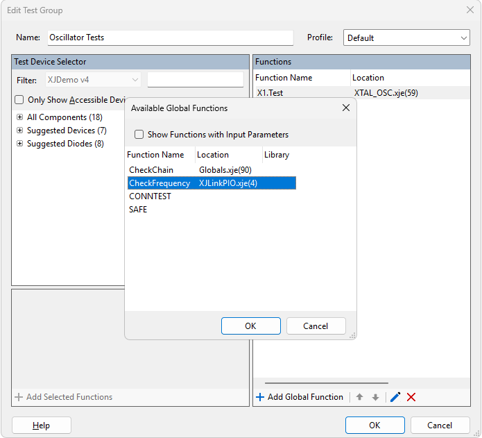
- Click OK on the Edit Test Group dialog.
- Click the Save button on the main XJDeveloper toolbar.
- Click the
 Run Tests screen button under the Run and Deploy header.
 - Select just the two tests in the Oscillator Tests test group to run.
- Click the
 Run button.
The Oscillator Tests now not only check that the clock is connected to the JTAG device but also that the frequency is within its functional operating tolerance.
Testing Oscillator X1...
Testing with device enabled...
Oscillator test took 93 ms
Oscillator output pin 3 detected 164 transitionsTesting with device disabled...
Oscillator test took 186 ms
Oscillator output pin 3 detected 0 transitionsX1.Test passed
Frequency of X1(7999958 Hz) within tolerance.
CheckFrequency passed
>>>> PASSED <<<<
These two functions return very different results. The standard boundary scan test from the XJEase Library can only sample the oscillator output once on every scan of the JTAG chain. When reading the frequency using the XJLink directly the actual frequency can be measured up to 200 MHz with an accuracy of 10 ppm.
Measuring voltage
XJLink pins can also be used to measure voltages up to 5 V as part of a test. In this section of this exercise you will add a test to measure the output of the potentiometer on the XJDemo board.
Pin voltages can also be seen in the Pin Details section of the Pin Mapping screen. Simply switch the Live Mode to On and the voltage will be displayed and continually updated.
The test function to take the voltage measurement will be added to XJLinkPIO.xje. The test will check whether the voltage read is within 10% of a target (expected) value.
- Click the Circuit Code Files screen button under the Setup header.
- Copy the code below and paste it at the bottom of XJLinkPIO.xje
/// Uses the voltage measurement capabilities of the XJLink
/// output by the potentiometer.
///
/// @param result Returns RESULT_PASS if the potentiometer is adjusted so that the voltage is in the range of 1 volt plus or minus 10%
GLOBAL CheckVoltage()(INT result)
  CONST INT EXPECTED_VOLTAGE := 1000;
  CONST INT PERCENTAGE_TOLERANCE := 10;

  INT margin := EXPECTED_VOLTAGE * PERCENTAGE_TOLERANCE / 100;
  INT actualVolts;

  result := RESULT_PASS;

  SAFE; // Ensure XJDemo board is powered before making measurements

  PRINT("Checking voltage on P1 pin 14 using XJLink voltage measurement.\n");

  // Read the voltage using the pin number rather than a PIO pin name
  actualVolts := PIN_VOLTAGE(PIO.POT);

  PRINT("Voltage read: ", actualVolts, " mV - ");

  IF actualVolts > EXPECTED_VOLTAGE + margin THEN
    PRINT("out of tolerance: max voltage allowed := ", EXPECTED_VOLTAGE + margin, " mV\n");
    result := RESULT_FAIL;
  ELSIF actualVolts < EXPECTED_VOLTAGE - margin THEN
    PRINT("out of tolerance: min voltage allowed := ", EXPECTED_VOLTAGE - margin, " mV\n");
    result := RESULT_FAIL;
  ELSE
    PRINT("within tolerance.\n");
  END;
END;
The CheckVoltage function uses the XJEase function PIN_VOLTAGE to measure the voltage of pin 14 on the XJDemo board's P1 connector via the XJLink.
The result variable is set to RESULT_PASS or RESULT_FAIL depending on whether the voltage read is within a PERCENTAGE_TOLERANCE of the EXPECTED_VOLTAGE.
- Click the Save button on the toolbar of the Circuit Code Files screen.
- Click the XJRunner Setup screen button under the Run and Deploy header.
- Click the Add Group... button at the bottom of the XJRunner Tests list.
- Set the Name in the New Test Group dialog to Voltage Test.
- Click the Add Global Function button at the bottom of the list of Functions.
- Select CheckVoltage from the list of available functions.
- Click OK in the Available Global Functions dialog.
- Click OK in the New Test Group dialog.
- Use the
 Up arrow at the bottom of the XJRunner Tests list to move Voltage Test to the top of the XJRunner Tests list.
 - Click the Save button on the main XJDeveloper toolbar.
- Click the Run Tests screen button under the Run and Deploy header.
- Select just the new Check Voltage test group to run.
- Click the Run button.
Checking voltage on P1 pin 14 using XJLink voltage measurement.
Voltage read: 1048 mV - within tolerance.
CheckVoltage passed - ran in default profile (All chains)
>>>> PASSED <<<<
This type of test could be used to check that the UUT is powered correctly before starting boundary scan testing.
Using PIO in XJEase tests
Measuring frequency and voltage on XJLink pins is useful. However, PIO pins can also be controlled as digital I/O during an XJEase test.
The next part of this exercise will use two PIO pins to drive one of the I2C busses on the XJDemo board to test the I2C ADC and EEPROM.
Using PIO pins as part of a XJEase test can be achieved in one of two ways:
- PIO pins can be directly referenced by using the PIO keyword in a SET statement.
- The connection between the XJLink and the UUT can be defined (on the Connections screen) and the test can be configured on the XJRunner Setup screen to make sure that the PIO pins are used to drive and read the nets.
This exercise will use the second method.
The connection between an XJLink2 and an XJDemo board is relatively simple and can be easily represented as a single device-to-device connection. The connection between an XJLink-PFxx controller and the XJDemo v4 board is more complicated due to the use of the adaptor board, and so needs to be represented as a set of individual pin-to-pin connections.
If any connection from the XJLink to the UUT is added to a project, all PIO pins on the XJLink will be used by the Connection Test. If you do not specify all the connections between the XJlink and the UUT (for example if you only define a single pin-to-pin connection) you may see false errors being reported when running the Connection test. For the limited application of this exercise the connections defined in the next section will suffice but in general you should add all connections so that XJTAG has all the relevant information about your circuit setup.
- Click the
 Connections screen button under the Setup header.
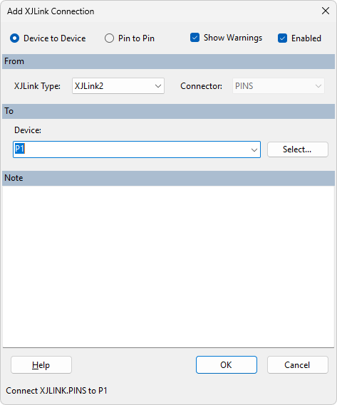
 - To the right side of the screen, in the XJLink Connections panel, click Add Connection... to open the Add Connection dialog.
If you are using an XJLink2 or PXI-XJLink2:
- Select the Device to Device radio button at the top of the dialog.
- In the From section make sure the selected XJLink Type is XJLink2.
- In the To section enter P1.
- Click OK to create the connection.
- Read the warning and click OK to continue.
If you are using an XJLink-PFxx controller:
- Select the Pin to Pin radio button at the top of the dialog.
- In the From section set the dropdown menus:
- Set the XJLink Type value to be XJLink-PF series.
- Set the Connector to be A.
- Set the Pin to be 11.
- In the To section select pin P1.6
- Click OK to create the connection.
- Read the warning and click OK to continue.
- Click Add Connection... again and follow the above procedure to also add a connection from XJLink pin A.15 to pin P1.8 on the XJDemo board.
- Click again on Add Connection... and add a ground connection between the boards by adding a connection from XJLink pin A.20 to pin P1.20 on the XJDemo board.
In most uses of PIO pins the frequency does not matter, but for an I2C bus it does because the devices on the XJDemo board have a maximum SCL clock frequency. The default speed of PIO depends on whether Optimised scans or Classic scans is selected on the Advanced Configuration Options tab. The default update-to-update interval for optimised scans projects like this one is 10000 ns which generates an SCL clock frequency of at most 50 kHz, which is lower than the rated maximum for the devices on the bus. There is therefore no need to reduce the speed further.
N.B. The default speed of PIO in classic scans mode is half of the TCK frequency. In both optimised scans and classic scans modes, SET_UPDATE_TO_UPDATE_INTERVAL can be used to adjust the minimum update interval for PIO, and RESET_UPDATE_TO_UPDATE_INTERVAL to return to the default.
- Click the Circuit Code Files screen button under the Setup header.
- Copy the code below and paste it at the bottom of XJLinkPIO.xje
/// Performs the I2C EEPROM and ADC tests but uses XJLink pins
/// to directly drive the SDA and SCL buses rather than using
/// boundary scan.
///
/// @param result Returns RESULT_PASS on success
///
GLOBAL PIO_I2C_Test()(INT result)
  // Run EEPROM test
  CALL("U5", "Test")()(result);

  // Add a blank line between test outputs
  PRINT("\n");

  // Run the ADC test
  CALL("U11", "Test")()(result);
END;
In this function the CALL keyword used to run the standard XJEase Library tests for the I2C EEPROM and ADC.
To run this function it must be added to the XJRunner Tests list .
- Click the Save button on the Circuit Code Files toolbar.
- Click the XJRunner Setup screen button under the Run and Deploy header.
- Click the Add Group... button
- Set the Name to PIO Tests.
- Click Add Global Function and add the PIO_I2C_Test function.
- Click OK to close the dialog and add the test group.
If the test were run at this point, the system would automatically select which pins it would use to drive and read the I2C busses and so it would not necessarily use PIO for both functions. In order to force the system to use the PIO pins, you need to configure the Bus Access settings for this test.
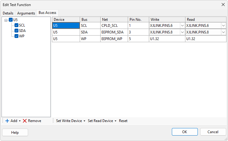
- Double-click on the PIO_I2C_Test test to open the Edit Test Function dialog.
- Select the Bus Access tab.
Because PIO_I2C_Test is in a Circuit Code File and not a Test Device File (which is associated with a specific device) the Bus Access tab does not display anything by default.
- Click the Add dropdown at the bottom left of the Edit Test Function dialog.
- Choose U5 from the list.
- Check the U5 checkbox to display all the busses in the Test Device File associated with that device.
- Use the Write and Read dropdown menus to change the SCL bus to use the appropriate XJLink PIO pin.
- Use the Write and Read dropdown menus to change the SDA bus to use the appropriate XJLink PIO pin.
- Click OK to close the dialog.
N.B. Because U5 and U11 are on the same I2C bus you only need to set the Bus Access values for one of these devices.
PIO_I2C_Test is now ready to run.
- Click the Save button on the main XJDeveloper toolbar.
- Click the Run Tests screen button under the Run and Deploy header.
- Select just the new PIO Tests test group to run.
- Click the Run button.
See Also
XJTAG v4.3.0