Identifying Power, Ground and Termination Voltage Nets
How XJDeveloper Identifies Possible Power, Ground and Termination Voltage Nets
XJDeveloper uses several methods to propose which nets are power or ground:
- Examining the names used for the nets (e.g. finding nets such as VCC, +5V, and GND)
- Examining what devices are connected to the nets (e.g. finding nets with many resistors connected to them that could be pull-resistors)
- Identifying nets with multiple capacitors connected to them
- Finding nets linked to a net already identified as power or ground via a ferrite bead, inductor, low value resistor (less than 10 Ω), or fuse
To identify nets that could be termination voltages, XJDeveloper applies the following methods:
- Examining the names used for the nets (e.g. finding nets such as Vterm and 0V9)
- Examining what devices are connected to the nets (e.g. finding nets that have resistors connected to them that might be termination resistors because of their value and where they're connected)
How to use XJDeveloper's Suggestions
The results of XJDeveloper's analysis are displayed in the Power/Ground Nets screen, part of which is shown in Figure 2.
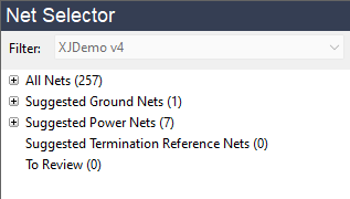
Figure 2: Identifying Power, Ground & Terminations
Expanding the + symbol beside each heading will show the nets that match XJDeveloper's criteria. In Figure 3 below the analysis suggests that the net labelled GND is a ground net. +1V8 and +3V3_MCU are suggested as power nets. A score expressing the confidence that a net belongs in a given category is listed to the right of the net followed by a summary of the criteria used to calculate the score.
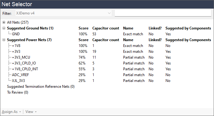
Figure 3: XJDeveloper's Power and Ground Net Suggestions
Nets can be categorised by moving them from the Net Selector section into the relevant columns as shown in Figure 4. It is recommended to follow the following process:
- Categorise nets with the highest scores first. If moving multiple nets as a group, be careful to check each individual net name first (see the warning below).
- Find all the linked power nets using the Links... button and categorise those nets.
- If the To Review category contains any nets review these nets and categorise them as appropriate.
- Once finished, review the categorised nets to check for errors—for example, to ensure no digital nets have accidentally been categorised as power.
This process is described in detail in the following sections.
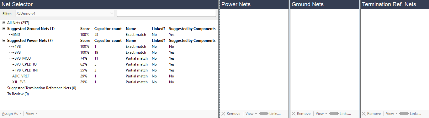
Figure 4: Assigning Nets
Moving nets to the appropriate category is done by highlighting the net and either dragging it with the mouse into the appropriate column, or using the Assign As dropdown menu at the bottom of the Net Selector pane. If a net appears multiple times in the Net Selector, it is only necessary to move the net once. If XJDeveloper's suggested categorisation is wrong, simply move the net to the correct column or, if it is not a power, ground, or termination reference net, leave it unassigned in the Net Selector.
- Never just categorise all net suggestions without checking them first as the suggestions are not guaranteed to be 100% accurate. Rather than moving all the suggested nets together as a group, assign the genuine power, ground, or voltage reference nets and leave any others uncategorised.
- If negative voltage power supply rails are being used, they should be categorised as Power Nets alongside any positive supplies.
- The schematic can be viewed at any time if a PDF schematic file has been added to the project (refer to the user guide chapter on Entering Board Information for instructions on how to add these files). The viewer can often help with the identification of nets: right-click on the net name and select Show in Schematic Viewer from the pop-up menu. The relevant net should then be shown highlighted in the viewer. If the net is not named on the schematic, it may not be possible for it to be found in this way, in which case the error "The search has returned no results" will be displayed. In that situation, select Explorer from the same right-click menu to see a list of devices connected to the net instead. Right-clicking on a device in Explorer and choosing Show in Schematic Viewer will then highlight that device's pin on the circuit diagram.
- These functions can also be accessed as shown below by selecting the net (1) and using the View dropdown menu (2) at the bottom of the section:
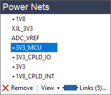
(1) (2)
If XJDeveloper has missed any power, ground or termination reference nets from its suggestions, they can be found by expanding the All Nets section and using the filter shown in Figure 4 above; they can then be assigned to the appropriate column(s) as before.
Assignments are saved by clicking the  Save button in the top toolbar.
- If an error is made and a net is placed in the wrong section, the categorisation can be changed as described in the section on Removing and Correcting Net Categorisations.
XJTAG v4.3.0