How to Create Your Own Test Device Files
Device files are assigned to devices during the device categorisation process, and it is normally during this stage that new files are created. Categorisation is performed in XJDeveloper’s Categorise Devices screen, which can be found under the Setup header:
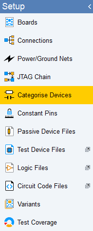
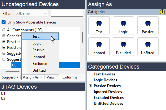
Figure 6: Test Device Files can be Created from the Categorise Devices Screen
When categorising a test device, XJDeveloper will examine the available BOM information and search the XJEase libraries for a matching file. If a suitable one is found, XJDeveloper will suggest it is used for that device. To categorise using the proposed file, click .
The example of Figure 7 shows the dialog that appears when categorising an NCD9830 ADC: because the BOM contained the part number, XJDeveloper has been able to find a matching device file and suggests it at the top of the screen above the horizontal grey separator bar. The lower part of the screen contains a list of recently used files, which can be a quick way to find files when a circuit contains several of the same device.
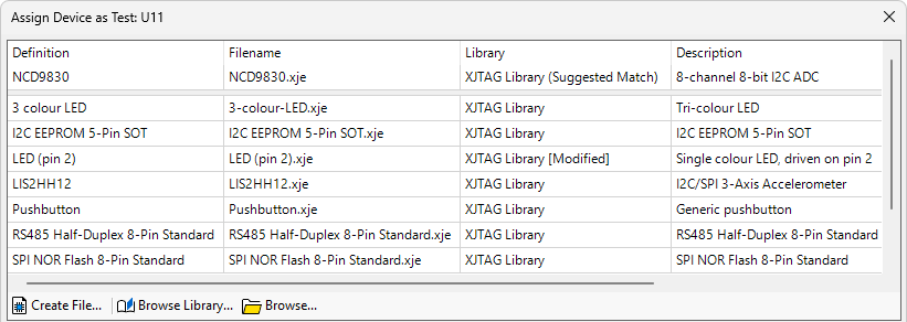
Figure 7: Assigning a Test Device File Using a Library Match
If a suitable file was not found, no Suggested Match is shown and only the list of recently used files is displayed as in Figure 8:
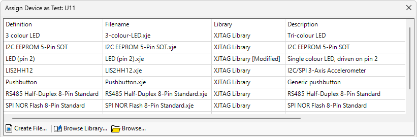
Figure 8: Assigning a Test Device File When no Library Match is Found
You can manually search the libraries for a suitable file by clicking (2) – this will be necessary if, for example, it wasn’t found automatically because the manufacturer’s part number was missing from the BOM data. If you have a file but it isn’t stored in a custom library, it can be located by clicking (3).
If you don’t have a suitable file, a new one can be created at this point. The process commences by clicking (1). The steps are illustrated in Figure 9, with each stage described in detail in the remainder of this chapter.
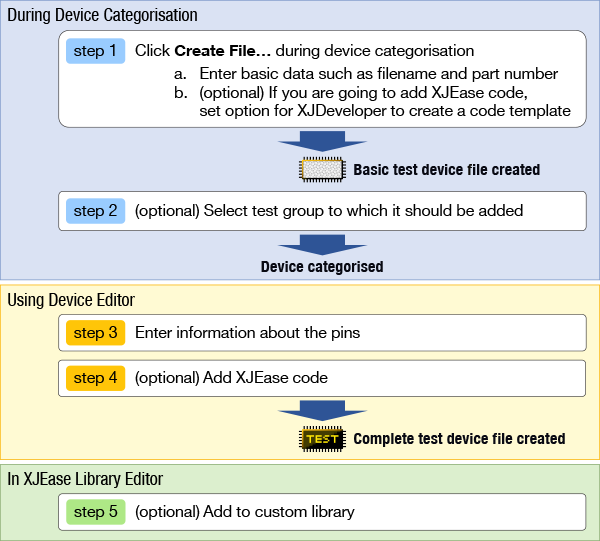
Figure 9: The Process of Creating a New Test Device File
Step 1: Starting to Create a New Test Device File
A new test device file is created as part of the process of categorising the device: in the Categorise Devices screen, find the device in the Uncategorised Devices list and assign it as a test device.
- To categorise a device as a test device, select it and click the Test tile or select from the Assign As menu at the bottom:
This causes a dialog box to open that allows a test device file to be assigned or a new one to be created:
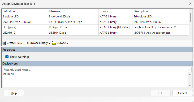
Figure 10: Creating a New Test Device File
- The dialog box shown in Figure 10 can be accessed at any time via the button at the bottom of the Categorised Devices list:
1. Select the device 2. Click to open the Configure Device as Test dialog box
To create the new file, click the button (see Figure 10 above), which will open the New Device File dialog box:
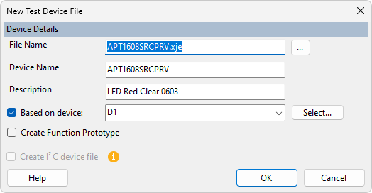
Figure 11: Entering Details for a New Device File
If suitable BOM data is available, XJDeveloper will use the part number and description fields to pre-fill the File Name (2), Device Name (3), and Description (4). These can be edited, or new values entered if desired.
- It is good practice to create test device files so that they can be reused in other projects. It is therefore recommended that the device’s part number is used for the File Name and Device name so that the device file can easily be identified later.
- An exception to this is if a device is being used in a non-standard way, in which case the test device file may not need to be re-usable. In this case, it is best to name the device with its circuit reference (e.g. U9.xje) so that this is clear.
There are several options available when creating a new test device file, selected using checkboxes —
-
Based on device (1): this is the recommended option to use because it is the fastest way to create a new file. Selecting this option tells XJDeveloper to allocate names to the device's pins based on the net names used in the circuit. For example, for a device with its clock pin connected to a net labelled SCL, XJDeveloper will automatically create a single-pin bus called SCL for that pin. Similarly, a multi-pin bus with clearly identifiable bits such as DATA7, DATA6 etc. will be grouped together into a single bus called DATA, with the pins in the correct order and DATA0 as the least significant bit.
By default, XJDeveloper will base the file contents on what it knows about the device currently being categorised. However, in a circuit containing several of the same device, you may wish to choose which of them is used to generate the bus names. To do this, select the desired device by clicking
Leaving this option unselected will create a file with an unpopulated bus list ready for you to fill in. This could be the best method if the netlist does not have meaningful net names or if you wish to access only a small part of a large device’s functionality (e.g. if the only intended function was a basic communication check over I2C, only two pins would require interaction). Note that if the Create I2C device file (6) box is also selected, the detected SCL and SDA pins will only be put on the SCL and SDA busses created by the I2C option - in this case, no busses based on net name will be created for these pins.
-
Create Function Prototype (5): if user-created test functions are going to be added to this device file, tick this box to insert a template into the file. If the file is only going to run code that resides in other files, the box can be left unticked (e.g. a test for an I2C device might only call the generic I2C protocol check, in which case no other test functions need to be added). Note that this option is unavailable if the Create I2C device file (6) box is selected.
-
Create I2C device file (6): if XJDeveloper has detected that the device being categorised is likely to be an I2C device, this option will be available. This is the best way to create a test device file for an I2C device, as it will automatically add IIC.xje (from the XJTAG library) as an additional code file, set up some required variables, create the SCL and SDA busses on the detected pins, and add an I2C-specific test function template to the new test device file. Hovering over the
 icon brings up a tooltip that explains what selecting this option will do and shows which pins were detected for the SCL and SDA busses.
Click to create the file, which returns the user to the Assign Device as Test dialog (figure 10).
- Notes can be added to the Properties section of the Assign Device as Test dialog box. This can be a useful place to insert a note that the file applies a disable value, for example, or to put a reminder that you need to come back to add some additional test functions, or to add an explanation about why the file was created.
The new test device file will now be shown highlighted at the bottom of the recently-used list. Before clicking , tests from the new device file can be allocated to a test group as described in the next section.
Step 2: Adding Tests from a Newly Created Device File to a Test Group
To make it easier to read the project's test list in XJRunner and to simplify the process of enabling or disabling multiple tests, it is possible to put tests into groups.
If the box was ticked when creating the test device file (figure 11), an Add Tests section will be present in the Assign Device as Test dialog – (highlighted in figure 12 below). This allows the test function in the device file to be assigned to a test group.
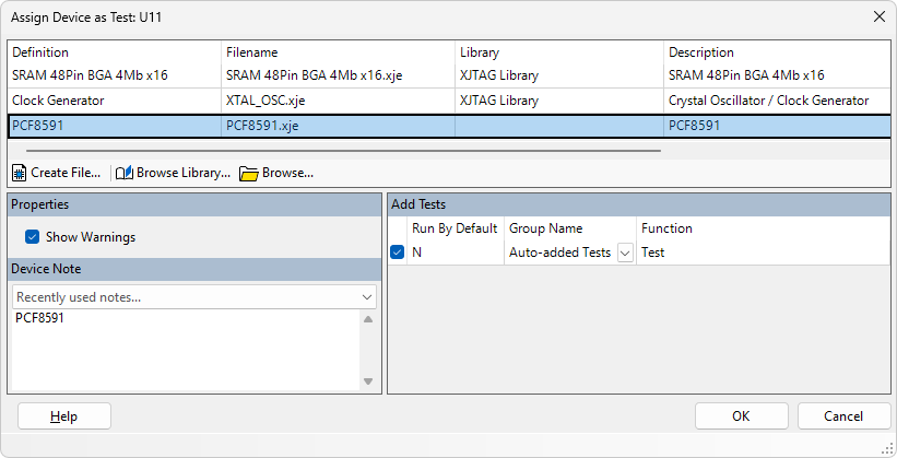
Figure 12: Adding a Newly Created Test to a Test Group
To add the test to a group:
- Keep a tick in box (1) (see figure 12).
- Set the required group in the Group Name box (3). By default, a new test will be assigned to a group called "Auto-added Tests". It can be reassigned to an existing group using the dropdown menu, or a new group can be created by typing a unique name directly into the box.
Note that the Run by Default option (2) identifies whether or not this test will be tagged to run by default in the project's test list. At this stage, it will be set to N because the test code has not yet been inserted into the device file. Later, this can be set to run or not run in XJDeveloper's XJRunner Setup screen.
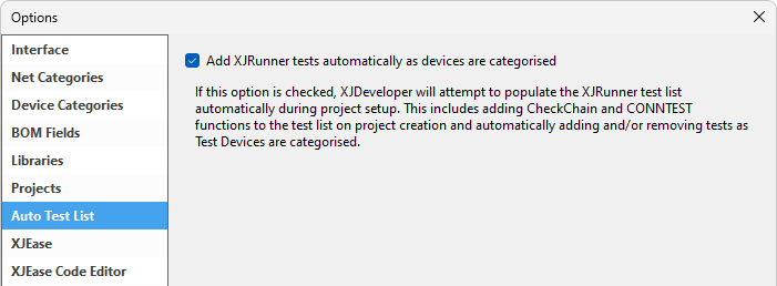
- Test functions will only be added automatically to the test list if the Auto Test List feature has not been disabled. This is controlled by the Auto Test List option - select from XJDeveloper's main menu, choose , and select the tab:
Once the Add Tests section has been completed, click to assign the new test device file. If the test is set to be automatically added to the test list, a warning dialog will be displayed. This pop-up can be disabled for the future by ticking the relevant box in the dialog. The user is now returned to the Categorise Devices screen.
The final steps are now to add pin information and any necessary test code to the newly-created test device file.
Step 3: Adding Pin Information
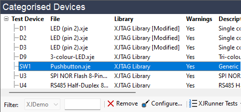
To make it easy to reference a group of pins on the device, bus names are allocated to collections of pins and/or individual pins. To add this information to a test device file, right-click the newly-categorised device in the Categorised Devices list as shown in Figure 13 and select the option from the context menu:
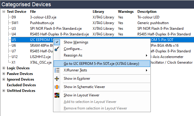
Figure 13: Selecting Editing of a Device File from the Categorised Devices list
This automatically transfers you to the Test Device Files screen and opens the new test device file in the editor as shown in Figure 14 below. Ensure the Busses tab is selected (1) to display the bus information. If the test device file was created based on a device in the circuit, the system will already have provided relevant bus names based on their nets, although some editing may be required.
If an empty file was created, bus entries will need to be added manually: click  Create Bus... (2) to create a new row and enter data directly into its columns. Once completed, the Busses list will look similar to this:
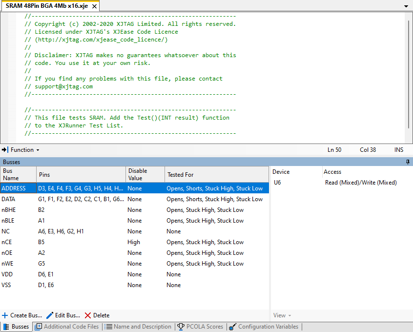
Figure 14: Entering Pin Information into a Test Device File
Each bus consists of a pin or group of pins on the device. The entries for each bus also show how the nets connected to that bus are to be set during JTAG chain initialisation (their Disable Value) and what additional test coverage the test function is adding.
As a minimum, all the pins to be interacted with during the test must be listed.
Panel (3) in Figure 14 above shows the level of access that is possible to the highlighted bus - whether a JTAG device can read it, control it, or both. When a JTAG device has different levels of access to the individual nets of a multi-pin bus, access will be shown as Mixed.
- In XJTAG terminology, a bus is the term applied to any group of pins that it is convenient to operate together, and also to single pins; it is not restricted just to the pins that the device's manufacturer defines as a bus. For example, you may wish to group several Enable pins into one bus so that they can be referenced as a single entity. A value can then be imposed on that whole set of pins using just one SET command. Grouping can also be used with power pins or pins that are not connected to keep the list short.
- To ensure the created test device file can be reused in other projects, it is good practice for the Busses list to include all pins that could be used in a test, even if the existing circuit being tested can't access them.
- It is not necessary to include the device's power / ground pins and any pins that are not connected in the device's package because they will not be tested. However, they can be added if desired (doing so can make it easier to check that no pins have been missed).
This bus list is more than a replica of the device's pin-out because it takes into consideration how the device is used, and a pin may therefore appear in several different busses. For example, consider a flash memory that supports quad-SPI: when in QSPI mode, its Write Protect and Hold pins are reallocated to provide extra pins for the data bus. The Busses list will therefore include a bus for Write Protect and a bus for Hold, but the same pins will also appear in the Quad-Data bus.
Each row requires four pieces of information:
- Bus Name: the name to be used to refer to the pin or group of pins. If the Based on device option was used, XJDeveloper will automatically populate this field based on the names of the nets connected to the pins.
-
Pins: the pin number(s) to be associated with that name. If entering more than one pin, separate them with commas (e.g. B7, D3, A2, C4). If multi-pin busses like address busses or data busses are being described, the pins should be entered with the most significant bit on the left.
If the Based on device option was used and there is an obvious bus (e.g. nets labelled DATA7, DATA6, etc.), XJDeveloper will automatically group those pins on to a single row.
-
Disable Value: is usually used to specify a default state that needs to be applied to the net(s) connected to that bus in order to stop the device driving any nets that would interfere with testing. It will be set to this state when the JTAG chain is initialised and during the Connection Test. As an example, if your circuit has a watchdog, you will probably need to disable it so that it does not cause random board resets during testing.
A Disable value can also be set to tell XJTAG what value will be driven by the device onto the net during testing. XJTAG can check that the value is indeed read, and will be able to use the value to work out expected values of any logic attached to the net.
A Disable value is entered by double-clicking in that column and selecting an entry from the dropdown menu. The options are:
- None - most busses will have the Disable value set to None. It means that is known that this device type will not drive this bus during the Connection Test and therefore it does not need to be held in any particular state. Consequently, no Disable value is needed and the test is free to set this bus to any state.
- Low, High - ensures the net(s) on this bus are held low or high by XJTAG during the interconnection test. This could be used for an Output Enable pin to prevent the device driving other nets.
- IsLow, IsHigh - these values are less commonly used and are not to be driven, but inform XJTAG that the net(s) on this bus are held low or high by the test device during the interconnection test. This allows XJTAG to check that the expected value is in fact seen on those nets.
- IsDriven - this value tells XJTAG that the net(s) on this bus are being driven by the test device during the interconnection test. XJTAG should not drive the net but should analyse its behaviour if it can be read, to check for shorts to other nets.
- Excluded - all controllable pins connected to this bus will be set to high-impedance during Connection Test. No JTAG devices will therefore drive the net during Connection Test, and the value read from it will be ignored. This would be used for a pin that it is known will be active, and no other device must therefore attempt to drive its net (e.g. this would be used for a clock oscillator output).
- Each bus's Disable value is applied at the end of the JTAG chain initialisation and persists until specifically overridden.
- Any bus settings that are changed before the Connection Test will be returned to their Disable values when the Connection Test is next run (because Disable values form part of a safe bitstream that is loaded into the JTAG devices at that point).
- Any bus with a Disable value will not be fully tested during the Connection Test so should be checked by an XJEase test to achieve good test coverage.
- Disable values can be overridden during an XJEase device test, but busses are not automatically returned to their Disable values at the end of that test. It is therefore important that any code interacting with busses that have disable values leaves them in a known state when it finishes.
- A Disable value is a useful way to ensure busses only become active when it is safe to do so. For example, because the setting persists after initialisation, it can be used to keep a memory interface in its inactive state during the majority of tests: it will not drive its data bus or respond to inputs until a device test overrides the disable values to check the memory’s functionality.
- There are often several ways to prevent a device from interfering with a test, and the method that requires the fewest pins to be set to Excluded is best: this keeps the number of nets that are not checked by the interconnection test to a minimum. For example, to prevent a memory from driving a bus, it is better to set a disable value on its nCE pin rather than setting the whole bus to Excluded.
-
Tested For: this column is used to tell XJDeveloper what test coverage will be achieved by running the device file's test function(s); this information is used by the test coverage report. Options are selected by double-clicking in the column and selecting from the dropdown list (multiple entries can be selected). The options are:
- Opens, shorts, stuck high, stuck low – when a test function controls a pin to check it's working, it will normally detect open circuits and stuck-at faults. Select the appropriate faults that the test functions will detect.
- Functionally tested — this is used when a pin is tested by being used rather than by being directly accessed by a net that is under boundary scan control. For example, although there may be no boundary scan access to an ADC's analogue input pins, it may be possible to check the voltages on those pins by reading the ADC. In that case, the analogue inputs can be listed as functionally-tested pins.
- There is no validation of the test coverage, so invalid settings in the Tested For column will not cause a warning and can result in incorrect test coverage figures. Any assumptions that were made about the circuit configuration around the device should therefore be checked to ensure they remain valid if the device is used in a different circuit (for example an ADC test may assume a fixed voltage is present on an analogue input, which might not be true in another circuit).
Values for the Disable Value and Tested For columns will have been set to when the bus was created and will need to be edited; new groupings of pins may also be required.
The contents of a row can be edited by double-clicking on a cell and entering a new value, or by highlighting the row and clicking the button to open the dialog box of Figure 15.
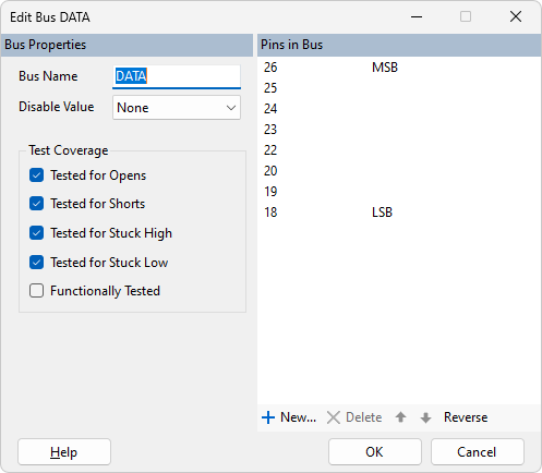
Figure 15: Entering Bus Details using the Edit Bus Dialog
The bus's name can be edited by typing into the Bus Name box, and a disable value can be selected from the pull-down menu. All pins in the bus are listed on the right. To remove one, select it and click the button; to alter its position in the bus, use the up/down arrows. To add a pin to the bus, click the button and provide the required pin number.
If the pins that make up the bus have been entered in the wrong order, clicking is a quick way to correct it.
Details of what test coverage will be achieved can be entered using the Test Coverage checkboxes on the left.
Controlling Pins on Other Devices Via the Busses List
To test a device, it is sometimes necessary to control a pin on a different device in the circuit. For example, in the circuit of Figure 16, a buffer generates four clocks from the output of an oscillator. If a test device file is created for U15, a method is needed to hold the Enable input of X1 high so that the oscillator will run. U15's test device file can then use the TestOscillator function (from the additional code file Oscillator.xje) to check its outputs for transitions.
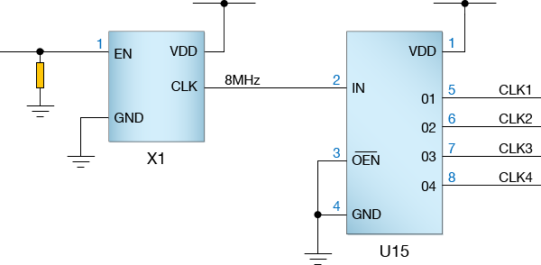
Figure 16: A Clock Buffer Circuit
X1's Enable pin (pin 1) can be controlled in U15's test device file (assuming it is accessible via JTAG) by making an entry in the Busses list of U15's test device file:
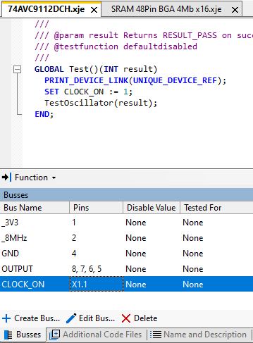
Figure 17: Controlling Another Device's Pin from a Test Device File
Click the button to make a new entry in the Busses list and give it a suitable name. Enter details of the pin to be controlled in the form <device reference>.<pin number> as shown in Figure 17 above, and create test code to set the net to the necessary state. XJDeveloper will work out a path to reach that net.
If a multi-board system is being tested, the board name must be included in the pin reference: <board name>.<device reference>.<pin number>.
- Although this method provides a quick way to control a net on another device's pin, the disadvantage is that the test device file is now only suitable for that particular circuit. An alternative is to create a circuit code file that calls two test device files – the first for X1 (to control its Enable input) and the second for U15 to test its four output pins. This method takes longer to develop because more files need to be created, but it does result in test device files that can be re-used in other circuit topologies.
Step 4: Adding Your Own Test Code
If required, test code can be entered in the top window of the same editor as shown in Figure 18. If the Create Function Prototype box was ticked when first creating the file, a template will have been inserted.
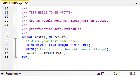
Figure 18: Function Template in a Newly Created Test Device File
- To turn line numbers on or off in the left margin, go to the View menu and select .
- To switch off the ability to collapse and expand sections of code, go to the View menu and de-select .
The template code can now be edited so that if performs the required tasks. See the section above on The Structure of a Test Device File for an overview of test functions.