Checking the Maximum Speed of Operation
Now that the JTAG chain's functionality has been verified, the next step is to check its high speed performance. The BSDL file includes a figure for the maximum TCK frequency that the part is guaranteed to run at across its operating temperature range. A higher speed is often achievable at room temperature, and performing a test to see how fast it will run at normal ambient temperature is beneficial: insufficient margin on a sample board would suggest there is a signal integrity problem that must not be ignored.
- Do not skip this test: it allows the user to identify problems with JTAG chains that might otherwise not be immediately obvious.
The test is initiated by clicking the Get Max TCK button at the bottom of the pin mapping screen, and the result of this test should be compared with the figure stated in the BSDL file of the slowest device in the chain.
- A good operating margin is expected: for example, if the BSDL file provides a figure of 10 MHz but the test only returns a maximum of 12 MHz, actions to improve signal integrity will probably be required to ensure the system works reliably. However, if something close to 25 MHz is achieved versus a BSDL file figure of 10 MHz, no signal integrity problems would be expected.
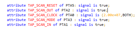
- The maximum TCK frequency is given the by TAP_SCAN_CLOCK attribute in the BSDL file (here it is 20 MHz):
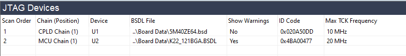
- It can also be viewed from XJDeveloper's JTAG Chain screen:
The biggest concern will arise if this test returns a figure that is less than the BSDL file's stated maximum frequency, in which case it is essential to find the cause: are any of the JTAG terminations missing? Does the cable grounding meet the guidelines? Is the cable too long? Is anything in the board design slowing down the signals?
If no obvious cause can be found, the JTAG Chain Debugger can be used to aid fault finding as described below.
If it has only been possible to achieve a small margin above the quoted maximum TCK, the impact should be determined by running the final signal integrity test. Fine tuning of slew rates and target terminations is also recommended in this situation if you are using an XJLink2 JTAG controller.
Altering the TCK Frequency
If the cause of the signal integrity problem has been found but cannot be rectified for a valid reason, it may be necessary to change the clock frequency used for testing.
- The TCK frequency setting at the bottom of the JTAG Chain Debugger is only a temporary setting and will be lost upon exiting the software. The only location where a frequency change can be made that will be persistent is within XJDeveloper as described below.
In an XJDeveloper project, a permanent change to the TCK frequency can be made by going to the Pin Mapping screen, which can be found under the Run and Deploy header. On the Pin Mapping screen select the Advanced Configuration Options tab.
The location of the TCK frequency control depends on whether the Optimised scans feature is enabled. When enabled, each JTAG subchain can have its own frequency configured, as shown in Figure 19. Double-click in the JTAG subchains table's TCK Frequency column to set the value for each chain, or reset it to the default value obtained from the chain's BSDL files.
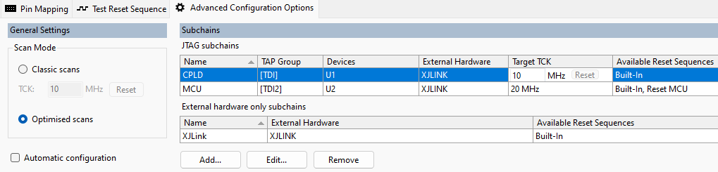
Figure 19: Making a Permanent TCK Frequency Change in XJDeveloper
When the Optimised scans feature is not enabled in a project, all JTAG chains will run at the same frequency, which is displayed as shown in Figure 20. Typing a new frequency (to the neareset 0.01 MHz) will override the default, which is the lowest value obtained from the BSDL files in the project, and the reset button will restore this default frequency value.
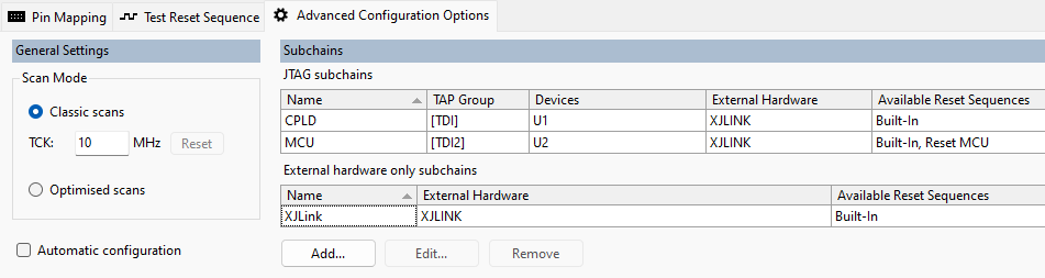
Figure 20: Making a Permanent TCK Frequency Change in XJDeveloper with Optimised Scans Disabled
- Signal integrity problems can have a variety of causes including frequency, terminations, signal rise and fall times, etc. Reducing TCK to solve such an issue without investigating and identifying the reason is never recommended because it can lead to random test failures.
A Final Signal Integrity Check Before Mass Production
A final automated signal integrity test is always recommended before the test transfers into mass production: if no errors are reported, the test system can be considered robust. This signal integrity test is particularly helpful if it has only been possible to achieve a small operating margin above the quoted maximum TCK frequency, in which case this test can indicate the likelihood of encountering problems.
The test is launched by selecting the Signal Integrity... option from the Check Chain dropdown menu at the bottom of the Pin Mapping screen as shown in Figure 21. A pseudorandom sequence that has been designed to trigger any signal integrity issues is now continually clocked through the chain; the received data is checked against what was sent, and the software flags any differences.
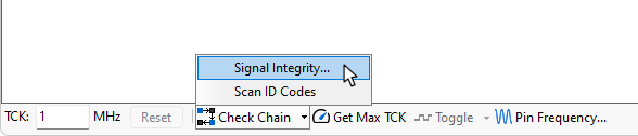
Figure 21: Launching a Signal Integrity Test
It is recommended that all four test modes are run for 10 to 20 minutes each:
- If no errors are reported in that time, the system is robust and ready for mass production.
- If just one or two errors occur per test, the signal integrity may be improved if you are using an XJLink2 by using the Slew and Target Termination settings. (XJLink-PF series controllers are designed not to require these settings.)
- Once 20 failures are detected, the software will stop and show the errors that occurred. Those errors should be logged and can be discussed with XJTAG's support team if debugging assistance is needed.
- When using the JTAG Chain Debugger, the test will run using the default TCK frequency at the bottom of the window and may need to be adjusted to the speed that will be used in production.
Adjusting Slew & Target Termination
If a very low rate of errors occurs (for example one or two per 5 minutes), the signal integrity for an XJLink2-based setup may be improved by adjusting the slew and target termination settings for TCK, TMS and TDI. This is done within the Pin Mapping tab: with the Use advanced settings box ticked and the relevant signal selected, the Target Termination and Slew Rate can be adjusted in the Pin Details section:
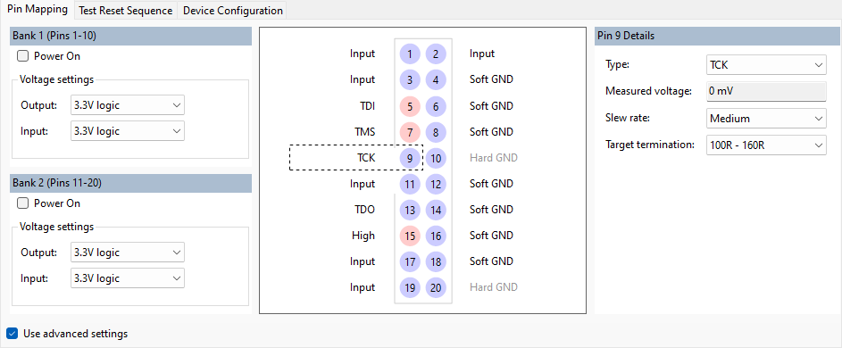
Figure 22: Pin Mapping Advanced Settings
- It is often best to set the 3 pins so that each has a different slew rate, rather than setting them all to Slow. This offsets the signal transitions from each other, which reduces the energy travelling along the cable and thereby reduces crosstalk.
Each time adjustments are made, the test should be re-run. Continue until no errors occur in a ten- or 20-minute period.
Enabling Long Term Success
Now all the tests and optimisations have been successfully completed, confidence can be high that your JTAG interface design will continue to perform reliably throughout the test system's lifespan. If changes are subsequently made to cables, or a production line is moved or a new one established, selected tests can be rerun to provide continued reassurance that performance has not been degraded.
XJTAG v4.3.0