Configuring the JTAG Devices
There are several settings for the JTAG devices that can be configured:
- Whether BSDL warnings are displayed
- The default mode for the JTAG device when it’s not being used
- Various IEEE 1149.6 settings
These settings are described in the remainder of this section.
They can be set while manually defining the chain at the point you provide its BSDL file. Alternatively, they can be set on the JTAG Chain screen after the chain has been defined by selecting the IC in the list of JTAG Devices and clicking Configure... at the bottom.
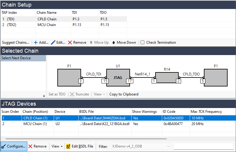
Figure 29: Configuring Settings for a JTAG Device After the Chain is Defined
Clicking Configure... allows the settings to be defined in the Configure JTAG Device dialog box:
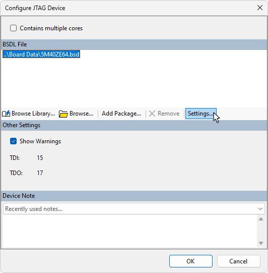
Figure 30: Configuring a JTAG Device After Defining the Chain
When configured during manual chain creation, the settings are defined in the Edit JTAG Chain dialog box, although the content is similar:
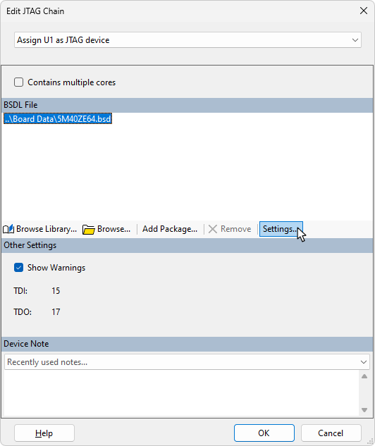
Figure 31: Configuring a JTAG Device During Chain Definition
Hiding warnings from the BSDL File
Many devices have warnings in their BSDL files that will be displayed in the Warnings tab at the bottom of the screen. A typical example from an FPGA is shown in Figure 32, which is a reminder that its BSDL file will require editing if the device is to be used in its configured state.
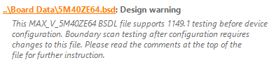
Figure 32: A Typical Warning Message from an FPGA's BSDL File
- For guidance on using configured devices in a test, refer to the application note on the XJTAG website.
Once these warnings have been read, they can be suppressed by removing the tick in the Show Warnings checkbox while entering the BSDL file: see Figure 30 and Figure 31 above (or it can be hidden later by clicking Hide in the Warnings tab at the bottom of the screen with the relevant warning selected).
- Removing the tick from the Show Warnings checkbox will disable all future warnings for that device, not just the current one. When it is just a JTAG device, this is unlikely to be a problem, but if it's also being used as a test device, it is best to leave warnings active until the project is fully debugged.
Setting a Default Instruction for JTAG Devices
During the connection test, all JTAG devices in the chain are placed into EXTEST mode. By default, when the system moves on to use your XJEase code to check the non-JTAG devices, any JTAG device that isn't used for a particular test will be switched into CLAMP mode (if available) to shorten the boundary scan chain. However, there can be some circumstances in which another mode is required. For example, if the circuit contains a JTAG-enabled Ethernet PHY and you want to run a loopback test, the PHY must be operational. In that case, you need to set the system so that the device is switched into BYPASS instead of CLAMP when it is not being used for boundary scan testing.
- You should only change the default away from NOT SET if you have a specific reason, for example because you need the device to be operational. In other situations, it is best to leave it as NOT SET to allow the system to select the appropriate mode for each point in the test.
- If a programmed device's default mode is set to BYPASS or SAMPLE, it is important to check that allowing it to run will not interfere with testing.
- If EXTEST or SAMPLE is selected as the device's default mode, the impact of not being switched into CLAMP when not in use will be a longer chain length and therefore a slower test.
To change the default mode, click Settings... to open the BSDL Settings dialog. You can now select the required mode from the Default Instruction menu as shown in Figure 33 below.
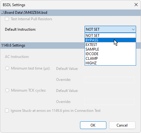
Figure 33: Changing the Default Instruction
- If an instruction other than CLAMP is set as the default, the selected mode will not be entered if the JTAG device is required to drive a net, for example, if it's needed to set a Constant pin or a Disable Value.
IEEE 1149.6 Settings
If the device supports IEEE 1149.6 testing, some related settings can be configured at this stage. These settings do not normally need to be changed from their default values and should only be altered if problems arise when running the Connection Test on 1149.6-enabled devices.
- Before changing any of these IEEE 1149.6 settings, XJTAG strongly recommends contacting the Support team.
If they need to be changed, click the Settings... button:
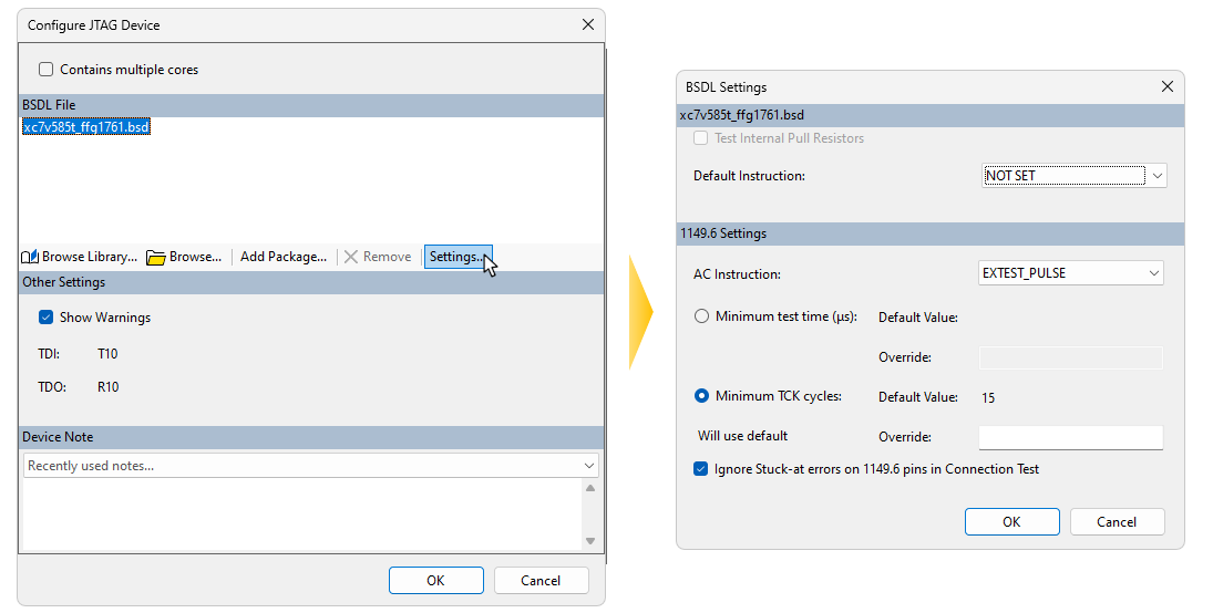
Figure 34: Changing 1149.6 Default Settings
Test Method
IEEE 1149.6 defines two mandatory test modes that devices must support: EXTEST_PULSE and EXTEST_TRAIN. The Pulse method is the one normally used and this is the default setting. In this mode, a single pulse is outputted that ends at the value of the required data bit. If the Train method is used, a sequence of alternating 0s and 1s is used, again ending at the value of the data bit. This mode can be used if the normal Pulse method does not work successfully for that device. The test mode is changed from its default setting using the AC Instruction dropdown menu (1).
To stop this device using its 1149.6 mode, select EXTEST mode from the menu, which limits the device to IEEE 1149.1 mode during 1149.6 testing.
- To disable all IEEE 1149.6 testing in a project, turn it off in the connection test settings rather than setting every device to EXTEST mode.
Setting a Minimum Pulse Length for AC Tests
When using the EXTEST_PULSE instruction, the minimum length of the pulse used for the test is set by default to the value stated in the BSDL file. If you are advised to alter this figure, you can override it by typing a new minimum value in microseconds into the Override box (2). Alternatively, the minimum length can be defined by a fixed number of TCK cycles by changing the selected radio button to Minimum TCK cycles and entering an override value.
If EXTEST_TRAIN is being used, a figure can be provided instead for the minimum number of pulses that must be sent between scans.
- These timing parameters (2) should only be altered under guidance from XJTAG Support. Reducing the value below the minimum figure in the BSDL file is likely to cause unexpected results; increasing it from the default is not recommended either – it is not normally a suitable way to solve problems.
Ignoring Stuck-at Errors
Some IEEE 1149.6 devices do not correctly implement all aspects of the standard, causing stuck-at faults to be reported on unconnected inputs. If this problem is experienced, you can insert a tick in box (3) to stop those errors being reported.
- Ignoring Stuck-at errors will reduce the test coverage so should only be used if necessary.
XJTAG v4.3.0