Types of Passive Device
Passive Device Description Files
XJDeveloper needs to understand the effect that passive components have on the circuit being tested. This information is provided by assigning Passive Device Description files (*.pdd) to relevant components during the device categorisation process. These files define the pins on the devices and the types of internal connections between the pins.
For example, a resistor pack used for series components would normally be assigned a file such as this:
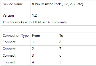
Figure 5: Typical resistor pack PDD file
This defines the type of connection between pins 1 and 8 as Connect. XJTAG uses several different Connection Types depending on the device's function in the circuit.
Commonly used Connection Types are listed below.
- Connect: used when a signal is unaffected when it passes between the pins – whatever digital level is driven on one side will be read on the other. This would typically be used for low value resistors, ferrite beads, links, etc.
-
Pull: used for resistors when one pin is connected to power or ground, and the other to a net that can be driven. Low value resistors cannot provide this type of connection because, with one pin tied to power or ground, it would not be possible to drive the other pin to the opposing logic state.
It is assumed that the pin that is not tied to power or ground would read the appropriate logic level when it is not being driven. This means that very high value resistors (e.g. greater than 500 kΩ) are unlikely to provide a reliable "Pull" connection because the undriven pin could take too long to reach its final value, causing errors to be reported.
- If a circuit has very high-value pull resistors (or capacitors that slow the logic transition), you should consider using the Connection Test option, Delay Between JTAG Scans. This will add some TCK cycles between scans to allow time for the signal to reliably return to its pulled state.
- Diff. Term: used for resistors placed across a differential signal. Because they have low values, they require a different Connection Type so that the apparent short-circuit detected during the connection test won't be reported as an error, while also telling the software it is acceptable to drive the two nets to opposite values during XJEase testing (unlike a device described as Connect).
- Bias Term: used for resistors that connect to a termination voltage. They have a unique Connection Type because they require specialised testing to ensure the software does not report spurious shorts between the terminated nets during the connection test.
- The other Connection Type available is Couple, which is reserved for the coupling capacitors used in IEEE 1149.6 circuits (not covered in this section).
XJDeveloper needs to differentiate between these Connection Types because they have different impacts on how tests are performed. Every passive component that is on a net that can be controlled from a boundary scan device, or which can be used to extend testing further into the circuit, should therefore be assigned a Passive Device Description file. These tell the XJTAG software how to deal with each device during testing.
The XJTAG library comes with files suitable for many passive components. Some of the commonly used ones are shown in the following table:
| Passive Device | PDD File | Connection Type | Comment |
|---|---|---|---|
| Jumper link with 2 pins | link (1-2).pdd | Connect | |
| Series resistor | resistor.pdd | Connect | Resistors between 0 Ω and 100 kΩ will be automatically suggested as series resistors if neither end is connected to a known power or ground net |
| Pull-up or pull-down resistor | pull-resistor.pdd | Pull | Automatically suggested for resistors between 1 kΩ and 100 kΩ if one end is connected to a known power or ground net |
| Ferrite bead | Ferrite Bead.pdd | Connect | |
| Inductor | Inductor.pdd | Connect | |
| Bias termination resistor | Bias Term Resistor.pdd | Bias Term | See the Termination Resistors section below for more details on bias terminations |
| Differential termination resistor | Diff Term Resistor.pdd | Diff. Term | See the Termination Resistors section below for more details on differential terminations |
| Resistor packs used for low-value series resistors | For example, 4 Pin Resistor Pack (1-8, 2-7).pdd | Connect | Different files exist depending on the number of pins and the pin-out |
| Resistor packs used for pull resistors | For example, 4 Pin Pull Resistor Pack (1-8, 2-7).pdd | Pull | Different files exist depending on the number of pins and the pin-out |
| Resistor packs used for bias termination resistors | For example, 16 Pin Bias Term Resistor Pack (1-16, 2-15, etc).pdd | Bias Term | Different files exist depending on the number of pins and the pin-out. See the Termination Resistors section below for more details on bias terminations |
The files for fuses, inductors, ferrite beads, and 0 Ω links all define a Connection Type of Connect between the device's pins. However, they are given different PDD files to make it easier to review the board setup.
Passive devices fitted to the board that are accessible from a JTAG device but which cannot influence any of the nets used during the test (such as ESD protection diodes and decoupling capacitors) should be set to Ignored instead of being assigned a PDD file.
As can be seen from the above, the type of connection used is dependent on how the device is used in the circuit. For example, a 1 kΩ resistor might need a PDD file that defines the connection between its pins as Connect or one that defines the connection as Pull depending on its application. When categorising passive devices, it is therefore important to understand how they are being used.
During the categorisation process, XJDeveloper will examine the circuit and propose appropriate PDD files for many of the devices.
XJTAG v4.3.0