Debugging Problems During Chain Checking
At the end of the test, the results pane will display output similar to this:

Figure 18: Typical Check Chain Results
If errors occur and the circuit contains multiple chains, the software will subsequently check the separate chains independently to see if any of them will run correctly.
Any errors must be cleared before continuing:
- If an early test fails (such as attempting to count devices), there is probably an issue with the physical connections, or there is a device not in boundary scan mode (which can occur if it is unpowered, in its reset state, or has a compliance pin that hasn’t been set). See the sections on Debugging DC Voltages and Using the Scan ID Codes feature for tools that can help trace the cause of such faults.
- If a read ID code does not match the BSDL file, compare the version of silicon the software reports is on the board to what is stated in the BSDL file.
- If problems are detected at speed but not when running at 100 kHz, investigate the signal integrity of the JTAG lines.
- Further help on debugging problems with the JTAG chain can be found in the JTAG Chain Debugger reference guide, in the XJTAG Help system.
Debugging Using the Scan ID Codes Feature
The JTAG Chain Debugger can be made to perform a continual cycle of a JTAG reset followed by a read of the ID codes. This allows a user to trace the signals through the chain using an oscilloscope. This mode is entered by selecting Scan ID Codes from the Check Chain submenu at the bottom of the window.
- If the JTAG chain consists of multiple devices, it must be remembered that data will be seen on the connector's TDO pin, even if an earlier device in the chain is malfunctioning (provided the final device receives TCK and TMS). The Scan ID Codes feature can be used to exercise the chain continually, which allows the user to trace the signals through the board and check for such faults.
- This feature can also be used to give an early indication of any signal integrity issues by leaving it running for several minutes: if additional ID Codes are reported during that time, the system is likely to be suffering from glitches, causing incorrect codes to be reported. If such problems are seen, items like grounding, crosstalk and high-speed termination resistors should be checked.
Issues Related to ID Codes Mismatches
A mismatch between the ID code read from the device and what is stated in its BSDL file is not uncommon. The four most significant bits of the ID code are the silicon version number: the manufacturer should provide a new BSDL file for each iteration but that does not always happen, especially with pre-release silicon. If the read version does not agree with what is in the BSDL file, it can be acceptable for the user to edit the silicon version number in the file to match, although this should be done with extreme caution.
- It is never acceptable to edit any part of the ID code other than the four most significant bits which denote the silicon version; if other bits do not match, the chip manufacturer must be contacted for the correct file.
- The silicon version is given by the four most significant bits of the IDCODE_REGISTER attribute in the BSDL file
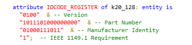
The 4 most significant bits indicate silicon version The LSB is always 1
- The BSDL file can either be edited so that the version number in the ID code matches what has been read, or X can be used to allow it to match several versions. For example, to match the first 4 iterations of silicon, the ID code can be modified to 00XX.
XJTAG v4.3.0