Defining Logic Devices
In this exercise you will see how to create a new Logic Definition which can be used when categorising a Logic Device. It will build on the completed tutorial project; a copy of this project is installed as a zip file: CompletedTutorial4.zip.
- Extract the zip file CompletedTutorial4.zip to a new, empty directory of your choice.
- Navigate into the Board Test directory.
- Open the XJDemo Board.xjd project from the extracted files, using XJDeveloper.
The XJDemo Board hardware is not required for this exercise.
Background
When you categorise devices on the Categorise Devices screen you can assign them to be Test Devices, Logic Devices, Passive Devices, Unfitted Devices, Ignored Devices or Excluded Devices.
Devices with functionality that can be described by a truth table, such as logic gates and buffers, should be categorised as Logic Devices.
N.B. Devices such as flip-flops that hold state cannot be categorised as Logic Devices in XJTAG.
There are two main benefits to categorising a device as a Logic Device:
- Connection Test - the connection test will fully exercise all of the elements of your Logic Devices that it can access.
- Non-JTAG testing - where you have a Logic Device between your JTAG enabled device and the non-JTAG device you want to test, the underlying system will automatically manipulate the Logic Device to achieve the outcome you specify. For example if you have a buffer between your JTAG device and your RAM, the underlying system will automatically control the enable and direction control signals as needed in order to write to and read from the RAM.
There is a comprehensive library of common logic definitions installed as part of XJDeveloper. This exercise is designed to help you when you have to work with a device that is not in that library.
Creating new Logic Definitions
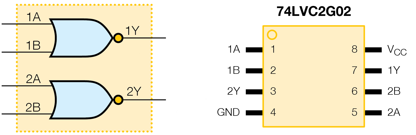
You are going to create Logic Definitions for two device types: first the dual NOR gate on the XJDemo board (U9) and then the RS485 transceivers (U4 and U7).
Dual NOR Gate
The logic symbol and pinout for U9 are shown below:
- Click the
 Logic Files screen button under the Setup header.
 - In the toolbar at the top select the Logic Definition dropdown menu and select the Create definition in Logic File... option.
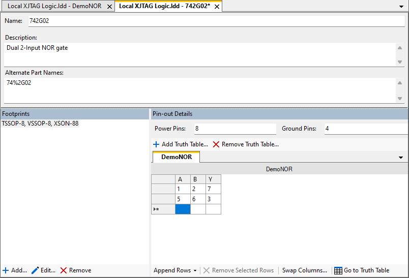
- In the Add New Logic Device Definition dialog ensure that the File is Local XJTAG Logic.ldd and in the Name field enter the text 742G02, then click OK.
- In the Add Truth Table dialog click on Create New Truth Table.
- Enter DemoNOR as the name for the new truth table and then click OK. (A new dialog box will then open, ready to add columns to the truth table.)
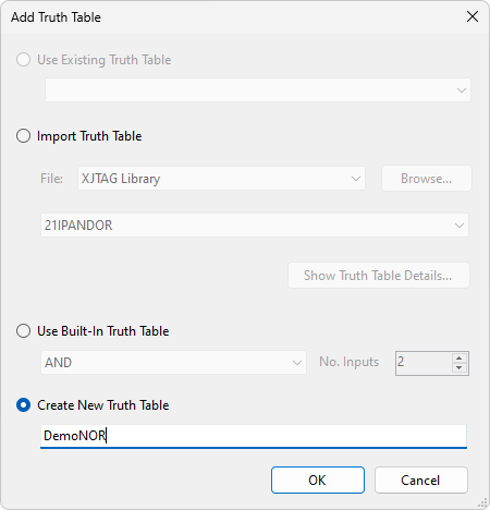
Normally you would choose the Use Built-in Truth Table option in the Add Truth Table dialog, which allows you to specify basic AND, NAND, OR and NOR gates of any width. For other types of gate the XJTAG Logic Library will often contain a suitable truth table. However, as an exercise, here you will create your own version of this truth table.
When you are creating a truth table you need to understand the structure of the device you want to categorise. In this case there are two instances of a simple NOR gate. The truth table only needs to define one of these gates as they operate independently from each other. You will then create two instances of the truth table in the Logic Definition to represent the two gates.
Add the columns to the truth table:
- Enter the column designators A,B,Y into the Add Columns To Truth Table dialog.
- Click on the OK button.
You have now created an empty truth table into which you can enter the logic behaviour for an individual NOR gate.
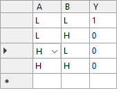
Each entry in the table must contain one of the following values:
- Inputs
- L - Low
- H - High
- X - Don't care - either low or high.
- Outputs
- Z - High Impedance
- 0 - Low
- 1 - High
- Click on the cell below A and use the dropdown menu to select L.
- Click on the cell below B and use the dropdown menu to select L.
- Click on the cell below Y and use the dropdown menu to select 1.
- Complete the remaining cells (shown below) to enter the truth table for a NOR gate.
- Set the Description to be Replacement 2 input NOR gate for XJDemo Board.
- Click on the
 Save button to save the new truth table.
For further information on entering and editing truth tables see Entering data into Logic Tables.
Now that the truth table is complete you can edit the Logic Definition to map the pins of the device into logic gates using the truth table you have just created.
- Click on the tab labelled Local XJTAG Logic.ldd - 742G02*.
- In the Description text box enter Dual 2-Input NOR gate.
- In the Alternative Part Names text box enter 74%2G02.
Alternative Part Names are used when searching for a model to use when categorising a device as a Logic Device. You can enter a full list of all of the possible part numbers however, as you can see, these part numbers can contain wild-cards to save you having to enter every possible variant.
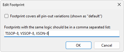
Each Logic Definition can contain multiple footprints for a particular part number. In some cases these footprints will have the signals connected to the same pins, however the system does allow you to define different signal locations as well. You are now going to enter the 8 pin footprints, all of which have the signals connected to the same pins.
- In the Footprints section select the Default name and then click
 Edit.
Edit. - De-select the option Footprint covers all pin-out variations.
- Enter the footprints in the text box as TSSOP-8, VSSOP-8, XSON-8.
- Click OK.
Now add the Power pins and Ground pins.
- In the Power Pins input box, enter 8.
- In the Ground Pins input box, enter 4.
All of the information that you have entered so far will make it easier to find and use the Logic Definition. Now you are going to enter the pin information to link the Logic Definition to the truth table.
- Click on the cell below A and enter 1.
- Click on the cell below B and enter 2.
- Click on the cell below Y and enter 7.
- Fill in the pin numbers on the second gate for the dual 2 input NOR (shown below).
- Click on the Save button to save the Logic Definition.
The Logic Definition is now complete, and can now be used for devices in the project. First we will remove the existing logic definition for U9:
- Use the Summary Statistics tab on the
 Test Coverage screen to verify that U9 initially has test coverage for shorts, opens, stuck-high and stuck-low faults on its 6 pins that are not on power/ground nets.
 - Click the
 Categorise Devices screen button under the Setup header.
 - Expand the list of Logic Devices in the Categorised Devices panel and select U9.
- Click on the
 Remove button at the bottom of the Categorised Devices section.
 - Return to the Summary Statistics tab on the Test Coverage screen to verify that U9 has lost most of its test coverage, now only having test coverage on pin 2.
Now the new definition can be added:
- On the Categorise Devices screen, select U9 from the Suggested Devices list in the Uncategorised Devices panel.
- Click on the Logic button under Categories in the Assign As section of the screen.
- From the Search File dropdown menu at the top of the dialog which appears select Local XJTAG Logic.ldd.
- Select the entry that you have just created - 742G02 Dual 2-Input NOR Gate.
- Select XSON-8 from the Footprint dropdown list.
- Click on
 Show Details to quickly check that you have selected the correct model.
 - Click OK to close the Logic Pinout Details dialog.
- Click OK to assign this definition to U9.
- Click on the
 Save button on the main XJDeveloper toolbar.
 - Finally, check again on the Test Coverage screen to see that U9 now has its test coverage restored to the original value.
Your project is now back in its original functional state but is now using the logic definition for U9 that you have created.
RS485 Transceivers
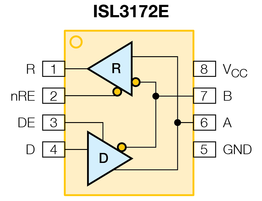
You are now going to create a Logic Definition that can be used for each of the two RS485 transceivers on the XJDemo board, U4 and U7. The logic symbol and pinout for this device type are shown below:
- Click the Logic Files screen button under the Setup header.
- In the toolbar at the top select the Logic Definition drop down menu and select the Create definition in Logic File... option.
- In the Add New Logic Device Definition dialog ensure that the File is Local XJTAG Logic.ldd and enter ISL3172E in the Name field, then click OK.
- In the Add Truth Table dialog click on Create New Truth Table.
- Enter RS485 Buffer as the name for the new truth table and then click OK.
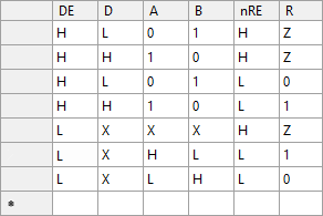
- Enter the text DE,D,A,B,nRE,R into the text box of the Add Columns to Truth Table pop-up to assign the column headers for the new truth table.
- Set the Description to be Logic definition for XJDemo board RS485 transceivers.
- Fill the truth table with the following logic behaviour:
- Click on the tab labelled Local XJTAG Logic.ldd ISL3172E*.
- Edit the default footprint name to MSOP-8.
- Edit the Power, Ground and Logic pins so that they match the pinout for the device (shown above).
- Click on the Save Button to save the Logic Definition.
Now we need to reassign the RS485 transceivers to use the logic definition we've just created.
- Click the Categorise Devices screen button under the Setup header.
- Under the list of Test Devices find the two RS485 transceivers U4 and U7 and reassign them to be Logic Devices using the logic definition you have just created - ISL3172E.
- Click on the Save button on the main XJDeveloper toolbar.
You will notice that some errors have appeared in the project:
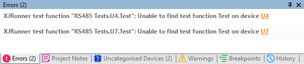
These errors are because XJTAG cannot find the Test Function it was using in the Test Device File for the two RS485 transceivers U4 and U7. This is because now that we have reassigned the transceivers the Test Device File is no longer associated with U4 or U7. With our new logic definition, XJTAG can automatically test U4 and U7 by verifying that each logic input state produces the correct output. This will be done by the Connection Test, and so there is no longer any need for the XJEase tests that were previously used - they can simply be removed from the test list.
- Click the
 XJRunner Setup screen button under the Run and Deploy header.
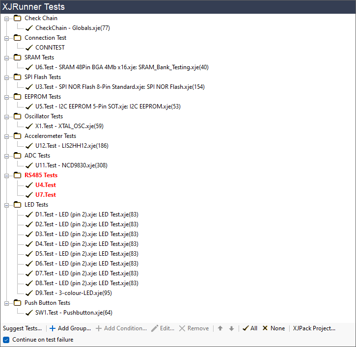
The RS485 Tests are in red to show that there is a problem with these tests.
- Select the Test Group by clicking on the text RS485 Tests
- Click on the Remove button at the bottom of the XJRunner Tests panel to remove the RS485 Tests from the test list.
- Click on the Save button on the main XJDeveloper toolbar.
The errors have now disappeared, but you will notice that you now have two devices listed in the Uncategorised Devices panel at the bottom of XJDeveloper.
- Click the Categorise Devices screen button under the Setup header.
- Expand the list All Components in the Uncategorised Devices panel.
You should see that P2 and R36 are now being reported as Uncategorised. By providing our logic definition for the RS485 transceivers U4 and U7 the system now knows how to control the RS485 pins A (U7.6) and B (U7.7). With this information we can now perform testing on other devices on the nets connected to these pins such as P2 and R36. When you categorise a device as a Logic Device it may change what you have access to so always check the Categorise Devices screen for any uncategorised devices.
- Categorise R36 as a Passive Device using the two pin definition Diff Term Resistor.pdd from the library.
- Categorise P2 as a Passive Device, by creating a new Passive Device File called RS485 Jumpers with links from pin 1 to 2 and pin 3 to 4.
- Click on the Save button on the main XJDeveloper toolbar.
You now have an alternate way of testing the RS485 transceivers U4 and U7 using logic instead of an XJEase test.
See Also
XJTAG v4.3.0