Power, Pin mapping and Test Reset Sequence options
This page of the wizard configures the JTAG interface of your XJLink JTAG controller.
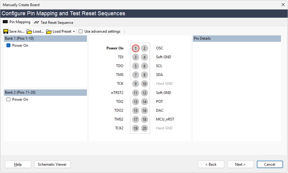
The Pin Mapping Tab allows you to specify how the pins on the XJLink should be used, and in the case of XJLink2 and its derivative controllers also allows you to choose whether or not you want to power your circuit via the XJLink2. Most circuits cannot be powered from the XJLink2 due to its low output power but the XJDemo board is small and simple enough that it can be.
Normally you would set the location of each of the JTAG pins on the XJLink's connector(s). For XJDemo v4 there is a preset pin mapping in the XJTAG software which will save time in this tutorial.
- Click Load Preset in the toolbar above the pin mapping diagram, and select XJDemo4 from the dropdown list.
- The pin mapping displayed here will match the one required by the XJLink you selected, either when creating the project or opening the Create Board Without Netlist wizard.
- If your board requires a Test Reset Sequence (TRST) to put one or more of the JTAG devices into JTAG mode, this can be set up on the Test Reset Sequence tab. There is more information on Test Reset Sequences here.
The next page in the wizard covers the association of the devices in the JTAG chain with their BSDL files.
Now that the JTAG connection to the board is specified, XJDeveloper will scan the JTAG chain when the Next button is clicked. It will read the ID codes from the devices in that chain, and match the ID codes with the files in the BSDL library that describe the implementation of JTAG on those devices.
- Ensure that the XJLink is connected to the Demo board
- Click Next > to move to the next stage of configuration.
- If you are using an XJLink2, you will be warned that powering your circuit in this way may damage your system. As the XJDemo board is designed to use USB power, click Yes to continue.
- If you are using an XJLink-PF series controller, ensure that the XJDemo board is connected via the adaptor board to connectors A and B, and that power is being supplied to the adaptor board.
XJTAG v4.3.0