Introducing the XJDemo v4.2 Board
Circuit Description
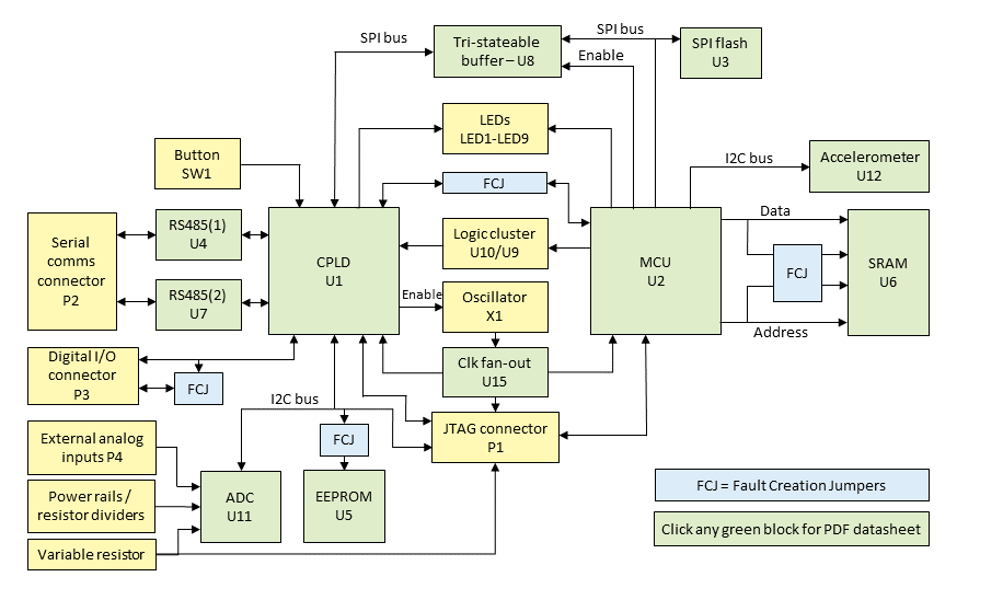
The circuit block diagram is shown above. Click one of the green devices to read its datasheet. The circuit schematic is also available in PDF format.
There are two JTAG-enabled devices on the XJDemo v4 board. U1 is an Intel Max V CPLD (5M40Z-E64C5N) and U2 is a NXP Kinetis microcontroller (MK22FN128VDC10).
There are also eleven other ICs on the board that do not have JTAG capability (non-JTAG devices). These are:
| Device Ref. | Part number | Description |
|---|---|---|
| U3 | W25Q80DVUXIE | 8 Mbit SPI flash memory, accessible from both the CPLD and the MCU. |
| U8 | 74LVC125A | Tri-stateable buffer, used to allow the CPLD to access the SPI flash. |
| U6 | IS61WV25616EDBLL | Static (256k × 16) RAM with its address, data and control signals connected to the MCU. |
| U11 | NCD9830DBR2G | ADC which uses an I2C interface connected to the CPLD and the P1 connector. |
| U5 | AT24C02D | EEPROM which uses an I2C interface, on the same I2C bus as the ADC. |
| U12 | LIS2HH12TR | Accelerometer which uses an I2C interface connected to the MCU. |
| U4 and U7 | ISL3172EIUZ | Half-duplex RS485 transceivers connected to the CPLD. |
| U9 | 74LVC2G02GS | Quadruple 2-input NOR gate device. |
| U10 | 74LVC1G04 | Single inverter. |
| U15 | 4AVC9112 | Fan-out buffer used for the 8 MHz clock signals. |
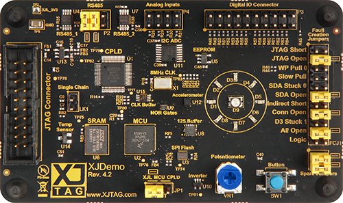
The Fault Creation Jumpers (designated FCJ1 on the board) will be used to simulate various faults on the PCB. The default connections that are needed for the board to operate correctly are shown below, and also marked on the silk screen of the board next to the jumpers.
In detail, the connections are as follows:
- FCJ1.3 to FCJ1.4 – this links the two halves of net COMMS_INT.
- FCJ1.11 to FCJ1.12 – this links the two halves of net SDA for the EEPROM.
- FCJ1.15 to FCJ1.16 – this links the two halves of net IO18.
- FCJ1.19 to FCJ1.20 – this links the two halves of net A8.
- P2.1 to P2.2 – this is part of the RS485 loopback.
- P2.3 to P2.4 – this is part of the RS485 loopback.
- JP1.1 to JP1.2 – this connects the nTRST pin of the MCU (U2) to the XJLink.
There are also two spare jumpers fitted (labelled Spare Jumpers) under the FCJ1 jumpers. These will be used to simulate faults during this tutorial.
XJTAG v4.3.0