Configuring Test Parameters
Various test parameters can be configured. For example, if a net can be driven from more than one source, it may be advantageous to force the test to drive it from a specific device and pin in order to achieve the best test coverage. As another example, some functions may have input parameters – for instance to provide a filename for programming – and those will also need to be set.
These configurations are done in the Edit Test Function dialog box and are described in the following sections. They include:
- Changing the name used for a function in the test list (Details tab)
- Defining a function's input arguments (Arguments tab)
- Selecting the device / pin that accesses a particular net (Bus Access tab)
The Edit Test Function dialog box can be opened from three places:
- While adding a function to the test list: if a function has input arguments, a pop-up box will automatically appear when the function is added to a test group to ask if you would like to set the parameters. Clicking Yes will open the Edit Test Function dialog box as shown in Figure 21 but with the Arguments tab selected.
- From the test list: test parameters can be configured later from the XJRunner Setup screen: double-click on the test in the test list or select the test function and click Edit... at the bottom of the list. This will open the Edit Test Function dialog box shown in Figure 21.
- While editing or creating a test group: with the relevant test function selected, click the
 Edit button:
 - The Edit... button at the bottom of the test list is context sensitive: when a test group is selected, it opens the Edit Test Group dialog; when a test is selected, it opens the Edit Test Function dialog; and when a condition is selected, it opens the Edit Condition dialog.
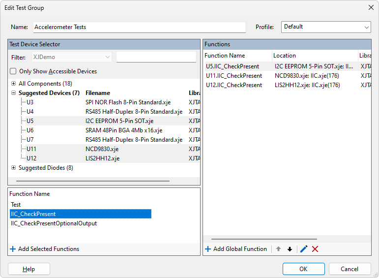
Figure 20: Editing a Test Function's Parameters from the New Test Group Dialog
The Edit Test Function dialog has three tabs:
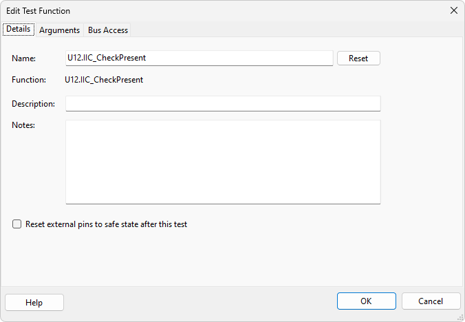
Figure 21: Using the Edit Test Function Dialog to Configure Test Parameters
Changing a Function's Name
Every test in a group must have a unique name so that conditions can reference the different tests. If a test function is added to a group that already has a function of the same name, the newly added one will automatically be given a suffix.
You may wish to change the name to clarify the purpose of the test. For instance, if several devices are being programmed, changing the tests' names from, for example, U6.ProgramFromFile and U7.ProgramFromFile to something like Program OS and Program Data can make the test list more understandable.
To edit the name of a test after it has been entered, click the Details tab and edit the Name field. To return the test’s name to that of its underlying function, click the Reset button.
A test with a name that has been changed is identified in the test list by  :
:
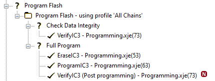
Figure 22: Test with Changed Name
Setting a Function's Input Arguments
Some functions may have input arguments that require configuring. For example, a function that performs programming will normally need to be passed a filename. Values for these arguments can be set when the test function is added to the test list or can be left for later. If they are not provided at that point, the function will be shown in the test list as having an error by being marked red. The input arguments can then be added / edited later from the test list on the XJRunner Setup screen.
When a test function that has input arguments is added to the test list, a pop-up dialog box will offer you the opportunity to provide values. Clicking Yes will open the Edit Test Function dialog box with the Arguments tab selected as shown in Figure 23 below. Values for each parameter can now be entered in the Value column.
Alternatively, the Edit Test Function dialog box can be opened later from the XJRunner Setup screen as described above, allowing new parameters to be entered and existing ones edited.
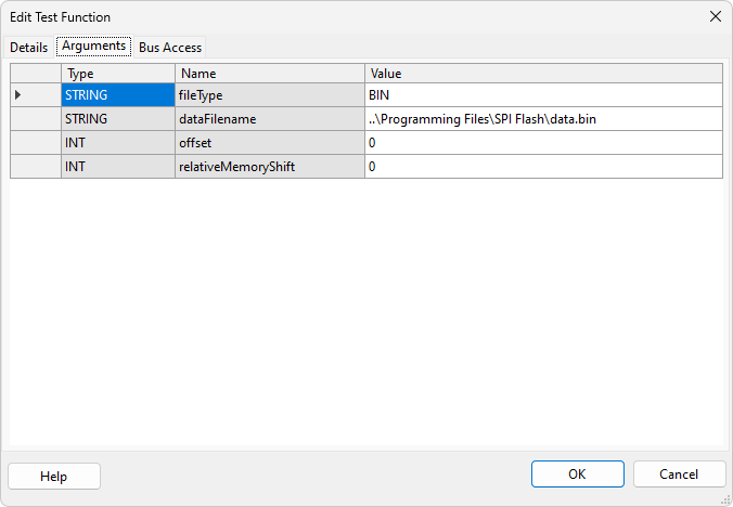
Figure 23: Providing a Test Function's Input Parameters
Functions with input arguments that have been set are identified in the test list by  :
:
Figure 24: Identifying Functions with Set Input Arguments
- If a function in the test list is marked in red, it indicates there is an error, which can be due to required input parameters not having been set.
Setting Which Pins are Used for Read or Write Access to a Device
There may be occasions when a net can be driven from more than one source. For example, consider the circuit in Figure 25, where the bus for a SPI flash can be controlled directly from the MCU or, via isolating buffers, from the CPLD. The pins on the flash can therefore be driven either from JTAG1 or from JTAG2.
In most cases, Connection Test will automatically check all paths but, in some situations, that may not be possible. For instance, in the circuit of Figure 25, the flash's Chip Select input needs to be held high during the connection test to keep the device inactive. A disable value therefore needs to be set for its Chip Select pin.
The requirement to keep that pin high prevents nets 1 and 2 from being fully tested. To maximise test coverage, it is therefore necessary to add a test to the test list to check the pins that Connection Test couldn't fully exercise.
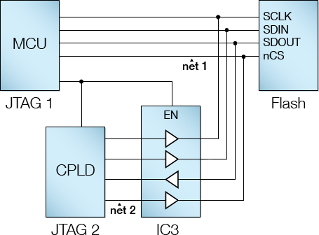
Figure 25: Circuit with Multiple JTAG Access Signal Paths
Another situation when the automated connection test cannot check particular nets occurs when a test device drives JTAG pins that cannot be used as outputs (for example because doing so would back-drive a logic gate’s output). This is another scenario when an additional test should be created to check the untested net(s). An example of this is illustrated by the clock distribution circuit of Figure 26 below.
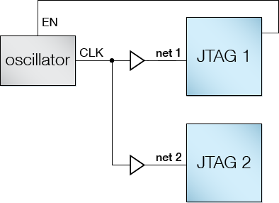
Figure 26: Clock distribution circuit
Nets 1 and 2 cannot be driven from the JTAG devices because they are connected to the buffer outputs. Connection Test will therefore not fully test the pins on those nets, and an additional test will be required. In this example, the circuit can be checked by using its functionality: controlling the oscillator’s Enable input will allow level transitions to appear on the JTAG devices’ pins, where they can be monitored. This checks nets 1, 2, EN, and CLK for open-circuit and stuck-at faults.
- To see which pins are currently untested, use XJDeveloper's Test Coverage screen.
In situations like those described above, where more than one output could be used for checking a test device, it will be necessary to ensure the additional tests use both outputs to maximise test coverage. In the clock example of Figure 26 above, a test that checks just the oscillator only needs to use one of the buffers. To extend the test coverage so that pins left unchecked by Connection Test are included, the function needs to be run twice – the first time using net 1, and the second using net 2.
In the SPI bus example of Figure 25 above, the new test needs to be run once using the MCU's output and repeated with the CPLD's output via the buffer to ensure both nets are checked.
Unless a test function is configured to use a particular output pin, XJTAG will automatically select one, and the nets driven by alternative output(s) will not be used. To make a test use a particular pin, you must edit the function to change the write access from Automatic to the pin required; how to do that is described in the following sections. The method is slightly different if the function is in a circuit code file rather than a test device file.
Adjusting Write & Read Access for Functions in Test Device Files
To force the test to use a specific pin to drive or read the nets, select the Bus Access tab in the Edit Test Function dialog as shown in Figure 27.
- It is only necessary to set the bus access for tests when a particular signal path is required – for example because Connection Test has not checked a particular net. In most cases, XJTAG can be left to select which pin to use to access a device.
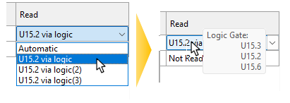
Each net has a Write column and a Read column because the signal path required to write a net may be different to the path used to read it (e.g. if one route is via a logic gate). When a net can be accessed via multiple paths, the setting will be Automatic by default, but can be changed by clicking on the dropdown menu:
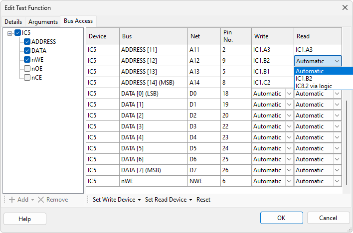
Figure 27: Forcing a Test to Use a Specific Pin
- When using the dropdown menu to select read or write access via logic, the pin shown in the menu is the logic device's pin that connects to the pin being tested. When boundary scan access to that logic pin can occur in different ways, it will be listed several times. To see all the logic device's pins that will be used for any particular option, select it in the dropdown menu and then hover over it. The tool tip will show all the pins on the logic device that will be used when accessing the bus with that option.','
- XJTAG cannot determine at compile time whether the required pins for driving and reading busses can all be selected simultaneously. If this is not possible then unexpected behaviour may occur.
- In particular, if a multi-bit bus can be accessed from either JTAG pins or via logic devices that have shared control signals, it is recommended that all nets in the bus are driven from a similar route: driving part of the bus from JTAG pins and some of the bits via logic gates can cause unpredictable results.
To return all the adjustable bus access settings to "automatic", click the Reset button as shown in Figure 27 above.
To set the access for all the bits of a bus that can be modified so that as many of them as possible use the same source, use the Set Write Device and Set Read Device buttons and select the desired device from the menu (Figure 28 below). When the chosen device can't be used for a particular net, the setting for that net will be left unchanged.
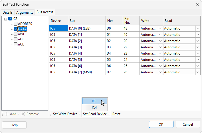
Figure 28: Setting Bus Access for Multiple Nets
Tests with modified bus access settings are marked in the test list with  :
:

Figure 29: Tests with Overridden Bus Settings
Adjusting Write & Read Access for Functions in Circuit Code Files
Circuit code files do not hold any bus information because they call test functions from test device files, and it is the test device files that hold bus details. To force a test that comes from a circuit code file to use a particular pin to access a net, it is therefore necessary to add the bus information into the test before the read and write access paths can be set. To do this:
- Double-click on the test in the test list to open the Edit Test Function dialog (or select the test and click Edit... at the bottom of the screen).
- Select the Bus Access tab as shown in Figure 30. Because circuit code files do not hold any bus details, the table will be empty.
- Click Add.
- From the menu, select the device referenced in the circuit code file's CALL statement. This will add a list of that device's accessible busses to the dialog box. Repeat to add busses for other devices if necessary.
- Insert ticks into the checkboxes beside the required busses, which will populate the Bus Access table.
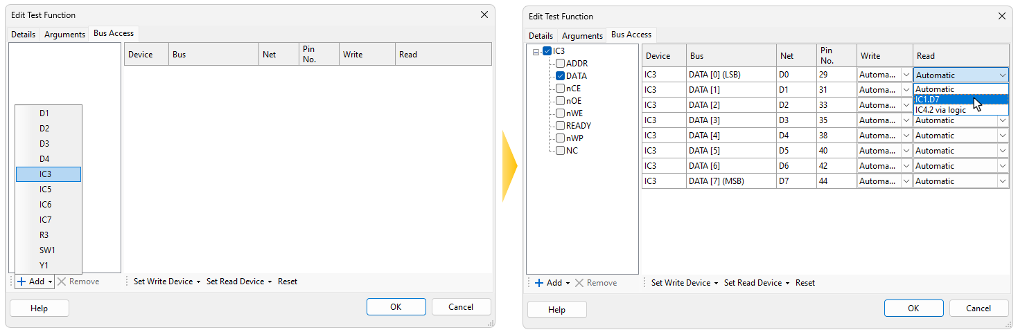
Figure 30: Adding Bus Access Details for a Circuit Code File Test
With the Bus Access table now available, continue as per Adjusting Write & Read Access for Functions in Test Device Files above.
XJTAG v4.3.0