Categorising the Remaining Devices
Components that XJDeveloper does not recognise will appear in the All Components list. This will include devices like switches, transistors, oscillators, and devices with reference designators that do not match the Regular Expression (regex) being used to identify component types.
- If XJDeveloper does not recognise a device because the reference designators used in your circuit are different to the regex settings in use (e.g. an LED referenced as LED1 rather than D1), the regex being used can be changed. See the section on Altering How Device Types are Identified for details of how to do this.
Categorising Transistors in Digital Circuits
A transistor may be categorised as Passive, Logic, or Ignored as shown in Figure 41, and the sections below give an example for each.
Figure 41: Options for Categorising Transistors
The first step in categorising a transistor is to check the level of access to its pins. This can be found using Explorer as described above in Determining the Level of Access in the Categorising Diodes section of this chapter.
Next, see how it's being used by viewing it on the schematic (right-click on the device and select Show in Schematic Viewer). In particular, it is important to establish which pin is acting as the circuit's input, and which as the output.
With that information, you can proceed to categorise the device as described below.
- Remember that access to the transistor will be reduced if devices on either side of it are uncategorised. If you do not have the access you expected, you should check the schematic to see if categorising another device first will improve the access.
Categorising a Transistor as a Passive Device
If the only transistor pin with write access is its base or gate, and any inversion the transistor might cause does not matter, it is simplest to categorise the device as Passive. The fact that a signal can only pass from input to output does not matter in this situation because the lack of write access to the output means that XJDeveloper cannot try to send a signal in the reverse direction.
For that scenario, a passive device file needs to be created with a Connect between the input and output pins. See the section on Creating a New Passive Description File for details of how to do this.
- Situations when a signal inversion does not matter include tests that flash an LED (because you are checking it's flashing rather than on or off) and when using the oscillator test from the XJEase library (because the test is looking for changes of state rather than a specific High or Low value).
Categorising a Transistor as a Logic Device
There are two scenarios in which a transistor would normally be categorised as Logic:
- When there is write access to both the input and output side of the transistor configuration. Categorising it as Logic tells XJDeveloper that the signal path is unidirectional and the test must therefore not drive backwards into the output when the transistor is turned on.
- When the transistor performs an inversion that's important for the test, and there is write access to the circuit's input. Categorising it as Logic allows XJDeveloper to be told about the inversion.
A Logic device file is required with a simple truth table to define the pin numbers for input and output and whether the transistor inverts the signal. Creating a logic device file in this situation is similar to creating one for a series diode – see the section above on Categorising a Single Series Diode as Logic for guidance. Which truth table to import depends on how the circuit is used and whether it inverts the signal.
Four truth tables are relevant when categorising a transistor as Logic:
- BUFOC is intended for circuits with a pull-up resistor on the output, where a Low input will drive the output Low, and a High input will place the output into a tri-state high-impedance condition. This truth table can only be used in circuits with a pull resistor.
- INVOC is also only for circuits with a pull-up resistor on the output, but where a High input drives the output Low, and a Low input results in a high-impedance output.
- BUF should be used when there's no output pull-up resistor and it's necessary for the system to understand that the output can be driven both high and low. A High input will cause a High output.
- INV is an inverting equivalent to BUF.
In most situations, BUFOC or INVOC are the most appropriate truth tables to use because most transistor circuits have a pull-resistor on the output.
However, if there is no pull-resistor, BUFOC and INVOC cannot be used because the system will not understand how to change the output between both states and will therefore consider the net untestable. For example, consider the circuit of Figure 42 below, where the transistor is providing a signal for a JTAG device, but an LED is used in place of a pull-up resistor. In that situation, the diode would be categorised as a test device rather than a pull-up, and the output net would therefore not have a known state when the FET is off. As a result, using the BUFOC or INVOC logic table for the transistor would be wrong because the system would then believe it had no way to set the output net high.
In this situation, it is important to claim that the output can be set high so that the system recognises the LED is testable, and therefore BUF or INV should be used (BUF can be used if the test causes the LED to flash because the state of the LED at any one moment is then unimportant).
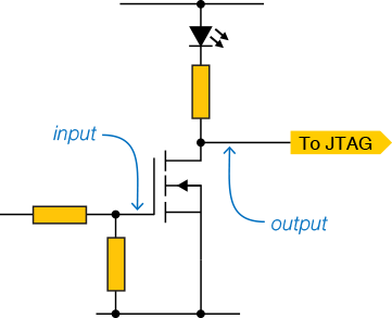
Figure 42: FET Circuit Where INV Truth Table is More Appropriate than INVOC
Categorising a Transistor as Ignored
When the transistor circuit's output goes to circuitry where there is no way to know what happens when the transistor is turned on and off, it can be categorised as Ignored provided it cannot affect the testing of the rest of the board.
If the transistor can affect other tests (e.g. because it's connected to a Reset pin), it will be necessary to prevent it interfering. There are two possible ways to achieve this:
- Provided the transistor doesn't need to be driven to keep its output in the correct state (e.g. because there's a pull resistor on its input), the transistor can be categorised as Excluded. This tells XJDeveloper not to drive any nets to which it's connected.
- If the transistor needs to be driven to keep its output in the required state, the transistor can be categorised as Ignored, and a Constant pin can be set to ensure it's held in the required state.
XJTAG recommends adding a note when prompted to explain why the transistor has been categorised in the way it has; this will be a helpful reminder when reviewing the project later.
Categorising Switches and Oscillators
If your circuit allows you to test devices like switches and oscillators, you should check the library manually to look for a suitable test device file: categorise the device as Test and then click Browse Library... in the Assign Device as Test dialog.
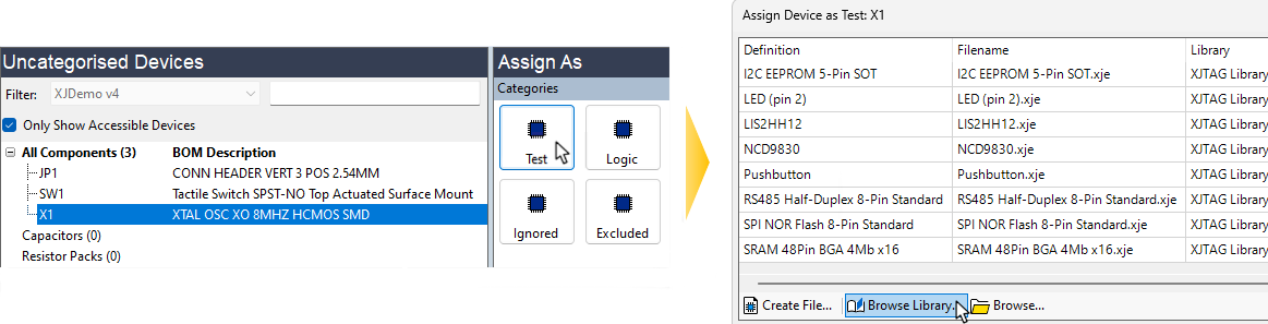
Figure 43: Finding a Suitable Library File
Test Device files for switches can be found in the Switches & Indicators section, and those for oscillators are in the Clocks, Oscillators & Crystals section (if necessary, select Categories from the View In menu in the XJTAG Library Browser window to list files by device type).
If a suitable file exists, the device can be categorised as shown in the Categorising Test Devices section. If an XJEase file does not exist, close the library browser to return to the Assign Device as Test dialog. A new test device file can then be created (or an existing one modified) as described in the user guide chapter on Creating Test Device Files.
XJTAG v4.3.0