Categorising Diodes
How diodes should be categorised depends on their circuit function and the level of access to their pins.
- LEDs that can be controlled
- Categorise as Test provided there is a way to confirm they illuminate (e.g. by asking an operator to confirm a flashing LED or by using external equipment).
- LEDs that can't be controlled (or if their illumination can't be checked)
- Categorise as Ignored.
- Series diodes
- Categorise as Passive or Logic depending on how they behave in the circuit.
- ESD diodes and similar protection devices
- Categorise as Ignored.
- Zener diodes
- Categorise as Ignored.
These categorisations are described in the following sections.
To decide how to categorise a diode, it's best to find out how it's used in the circuit first and then to check the level of access to each pin.
To check its function by viewing it on the circuit diagram, use the Tools menu and select Schematic Viewer > Device... and then type the device reference into the box at the top of the Device Selector window.
Determining the Level of Access
To determine what access there is to the diode's pins, return to the Categorising Devices screen, right-click on the diode (probably in the Suggested Diodes list), and select Show in Explorer. Explorer will show something similar to Figure 26:
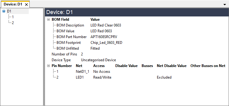
Figure 26: Using Explorer to Check Access to a Device
The Access column shows the level of access to each pin. The example above shows a diode with JTAG read and write access to its cathode (pin 2). It is important to note how the device's pins are referenced in the netlist so that the correct model file can be assigned (a diode with pins A and K will require a different file to one with pins 1 and 2).
- More information on using Explorer can be found in the chapter on Finding Information Using Explorer & Viewers.
With information on which pins are accessible, how they're connected in the circuit, and how the netlist references the pins, the diode can now be categorised as described in the following sections.
Categorising LEDs
LEDs can often be tested by using boundary scan to drive the net that controls them, and confirming they illuminate correctly, either with external equipment or by using a message box to ask the operator to confirm they're functioning. In those cases, the LED should be assigned as Test. See Categorising Test Devices above.
If you don't want to interact with an LED, it can be categorised as Ignored. In that case, the pins will still be tested for shorts and stuck-at faults as part of the connection test; it is only the open-circuit and illumination checks that will be lost.
XJDeveloper's library of test device files includes files for single LEDs called LED (pin 1), LED (pin 2), LED (pin A) etc., and others for multi-LED packages. The test function they call flashes the LED and uses a dialog box to ask the operator to confirm the LED is functioning correctly. It is important to select the file with a pin-out that matches your circuit. LED (pin 1) is for a single LED with pin 1 accessible, and LED (pin 2) is for a single LED where it's pin 2 that is accessible. If a suitable file is not available, a new one can be created based on an existing file – see Creating Test Device Files for details of how this is done.
The LED files in the XJTAG library have configuration variables that define an off state and set whether an operator is asked to confirm the LED colour. The off state is the value that the net driving the LED will be left in after the test; it has a default setting of Tri-state. When the LED is driven via logic, this default setting might need to be changed to High or Low because not all logic gates can provide a tri-state (high impedance) output.
When an LED is being categorised as a test device using a library file, the Assign Device as Test dialog box will allow any configuration variables to be set. Once the file has been selected, the values can be entered in the dialog as illustrated by the example in Figure 27.
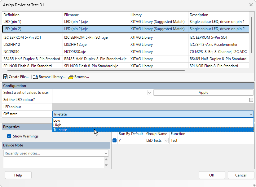
Figure 27: Setting an LED's Configuration Variables
When selecting a file from the library, the Details tab shows which LED pins the code assumes can be driven, allowing you to choose the correct file for your circuit configuration. The following example shows a multi-LED package:
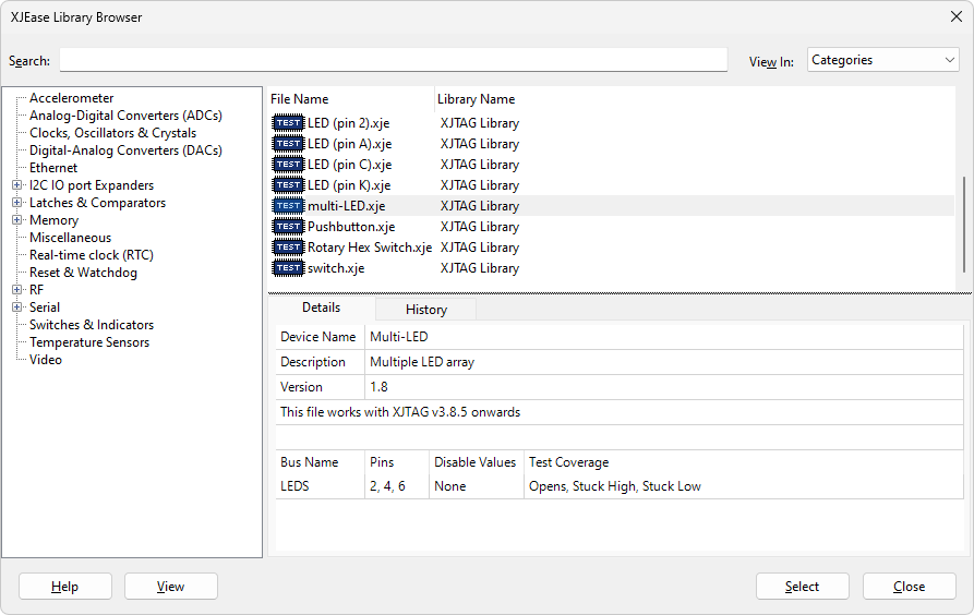
Figure 28: Checking Which Pins are Used by a Library File
Once a file has been selected, its details will be displayed in the Assign Device as Test dialog box in the same way as when accepting XJDeveloper's proposed file (Figure 27 above). Set any configuration variables and click OK to save the categorisation.
- XJDeveloper identifies diodes by the reference designator D followed by a number. If LEDs in your circuit are identified with a different prefix such as LED or DS, you can modify the regular expression that XJDeveloper uses to match LEDs, as described in Altering How Device Types are Identified below.
Categorising Series Diodes
Series diodes may need to be categorised as Passive or Logic depending on how they're used in the circuit.
Categorising Series Diodes as Passive
In the circuit of Figure 29, a series diode is used in conjunction with a pull-up resistor to allow a JTAG device to reset an IC that is powered at a lower voltage than the JTAG IC.
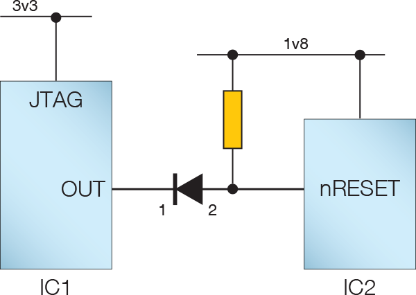
Figure 29: Series Diode that can be Categorised as Passive
In this example, the nRESET pin can only be driven from IC1. There is therefore no difference in the signal's behaviour in boundary scan mode between that circuit and one where the diode is replaced by a link. In this case, it is therefore acceptable to categorise the diode as a passive device.
To do this, categorise the diode as Passive and, when prompted to assign a file, create a new passive device file with a Connect between its pins. For guidance, refer to Creating a New Passive Device Description File below.
- To make the test project easy to review, it is best to give the new file a relevant name such as diode.pdd, and to add a description to the file that explains when it can be used.
Situations in which it is not applicable to categorise a diode as Passive are:
- when there is boundary scan access to both sides of the diode.
- when several diodes are used in combination, and you need the system to understand how to control the individual diodes to achieve a particular value on the circuit's output (e.g. diode OR and AND circuits).
In those circumstances, a series diode will need to be categorised as Logic instead. This is described in the next sections.
- Further guidance on deciding how to categorise a device based on its use in the circuit can be found in the section on categorising transistors.
Categorising a Single Series Diode as Logic
In Figure 29 above, the signal could only flow from left to right. However, if IC2 was a JTAG device, categorising the diode as Passive would result in the system believing the signal flow was bidirectional, which would lead to errors. In that case, the diode needs to be categorised as a logic device so that the system understands the signal flow is unidirectional.
In the Categorise Devices screen, perform the following steps:
- Select the diode and assign it as a Logic device. This will open the Assign Device as Logic dialog (Figure 30).
- Click Create Definition... to open the Add New Logic Device Definition dialog.
- Use Browse... to select the project's Logic file (Local XJTAG Logic.ldd).
- Provide a suitable name for the new logic definition. For ease of reuse, it is best for the name to state which pin has write access.
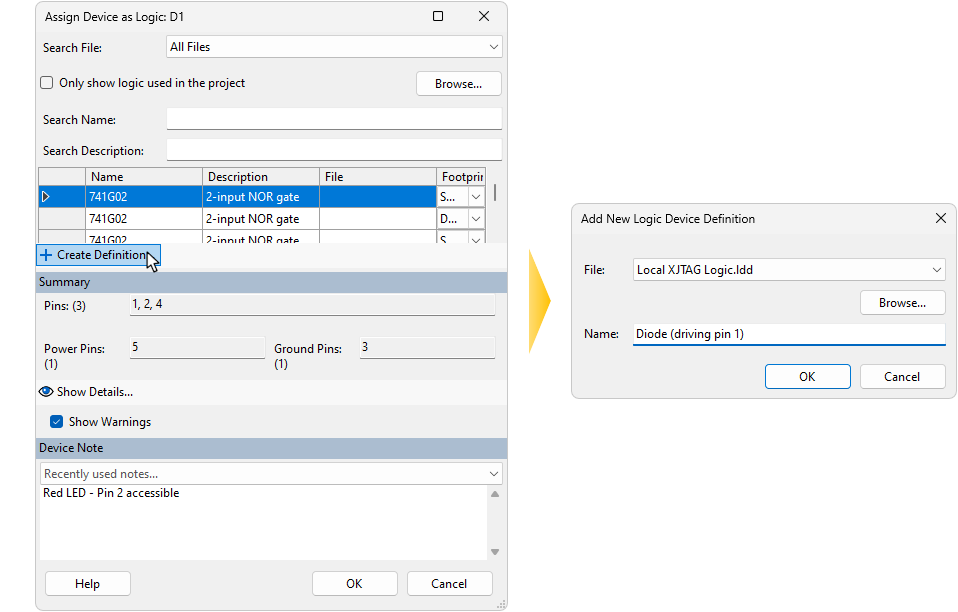
Figure 30: Creating a Logic Definition for a Diode
Click OK to create the entry, and you will be returned to the Assign Device as Logic dialog. Click OK to complete the assignment.
It is now necessary to add a truth table to the newly created entry: right-click on the device in the list of categorised logic devices and open the definition by selecting Go to.
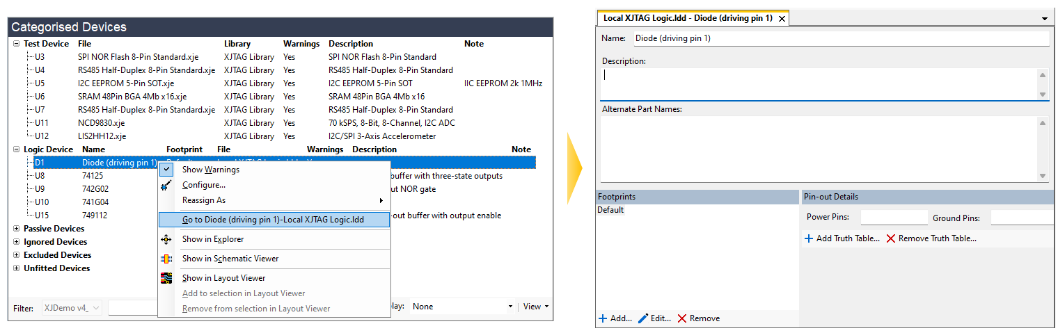
Figure 31: Adding a Truth Table to a New Logic Device Definition
In the bottom-right of the screen, click Add Truth Table... (Figure 31 above). This opens the Add Truth Table dialog box as shown below. Select the Import Truth Table radio button and choose BUFOC (a non-inverting open-collector buffer) from the dropdown menu. This will assign a simple truth table with an input called In1 and an output called Out. Choosing BUFOC rather than BUF allows the pull resistor to be included in the test (refer to Figure 29 above).
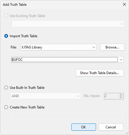
Figure 32: Defining a Truth Table for a Single Series Diode
Click OK to add the truth table, and you will be returned to the Logic Files screen. The next step is to assign the diode's pins to In1 and Out by typing directly into the pin table as shown in Figure 33 below. In this example, it's pin 1 that's being driven and is therefore defined as the input, but you will need to check the diode's pin-out for your circuit.
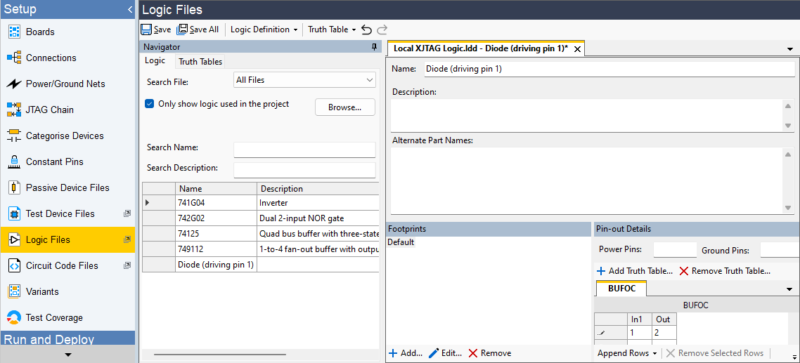
Figure 33: Adding Pin Mapping to a Logic Device
Once the pin numbers have been entered, click  Save to save the logic definition as shown above. To continue categorising, return to the Categorise Devices screen.
Categorising Diode Logic Configurations
Consider the logic functions performed by the diodes in the following circuits when there is access to both inputs:
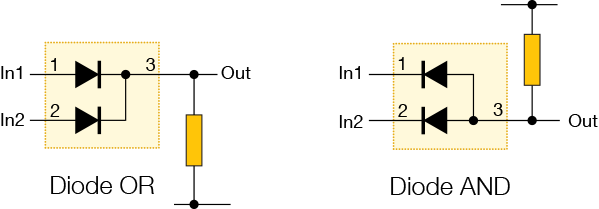
Figure 34: Diode Logic Configurations
In these situations, the system needs to understand that it must control both diodes to achieve a particular logic value on the output. The combination of diodes therefore needs to be categorised as a single logic device, and a new Logic Definition created. How this is done depends on whether the diodes are in the same package or whether they are separate components.
(i) Diodes in the same package
If both diodes are in the same package, perform the following steps on the Categorise Devices screen:
- Select the diode and categorise it as Logic. This will open the Assign Device as Logic dialog (Figure 35).
- Choose where the new logic device definition is to be stored: click Create Definition... to open the Add New Logic Device Definition dialog. This will default to saving the new definition in the Local XJTAG Logic.ldd file, which is correct for most projects. Browse... can be used to locate a different location if required. Previously used alternatives will be listed in the dropdown menu.
- Provide a suitable name for the new logic definition. For ease of reuse, it is best for the name to include details of how the pins are connected.
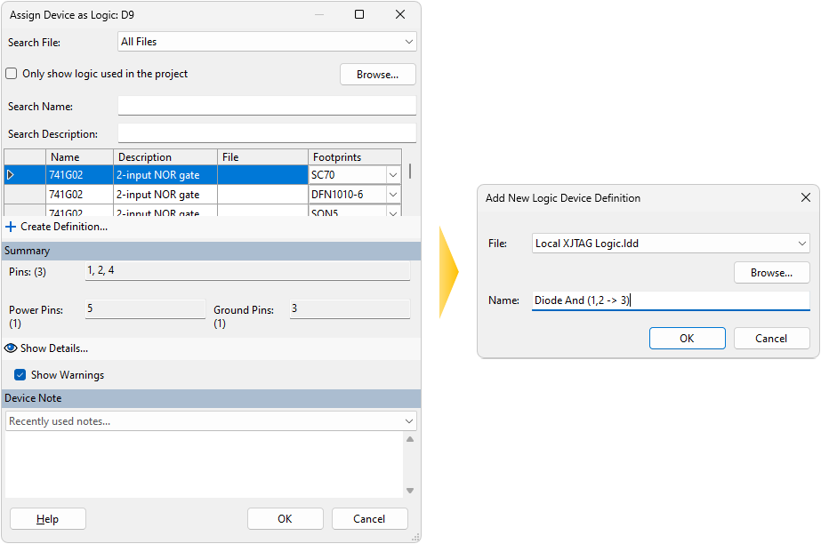
Figure 35: Creating a Logic Definition File During Categorisation
Click OK to create the entry, and you will be returned to the Assign Device as Logic dialog. Click OK to complete the assignment.
It is now necessary to add a truth table to the newly created entry: right-click on the device in the list of categorised logic devices and open the definition by selecting the item starting Go to from the menu. This will switch you to the Logic Files screen and open the newly created logic device definition.
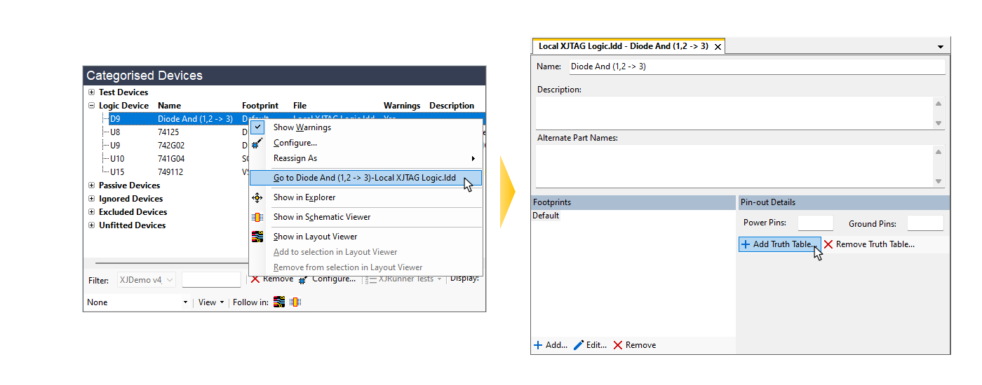
Figure 36: Adding a Truth Table to a New Logic Device Definition
In the bottom-right of the screen, click Add Truth Table... (Figure 36 above). This opens the Add Truth Table dialog box, in which you can either select a standard table or create your own. For the example of two diodes providing an AND function (Figure 34), the two-input ANDOC table can be selected from the dropdown list and imported:
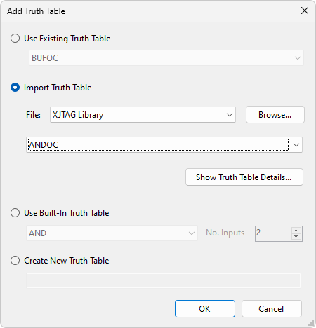
Figure 37: Importing the ANDOC Truth Table
The ANDOC truth table has been selected because the twin-diode package has a pull-up resistor connected to the output. This truth table allows the resistor to be tested during the connection test.
Once the truth table has been added, the diode package's pins can be mapped to the truth table's inputs and output by typing directly into the pin entry table:
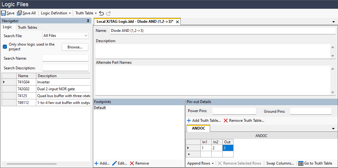
Figure 38: Mapping the Diode's Pins to the Truth Table
Once the pin numbers have been entered, click Save Definition as shown in Figure 38. To continue categorising, return to the Categorise Devices screen.
(ii) Diodes in separate packages
If the diodes that provide the logic function are in separate packages, a circuit-specific logic file will be necessary. The procedure is similar to above except the entered pin numbers must now include the diodes' reference designators. For example, consider the OR circuit shown in Figure 39 below that consists of D1 and D2. In this instance, the two inputs are D1.1 and D2.1. The process is to categorise one of the diodes as before (in this example, D1 has been chosen) and assign the logic definition to the chosen diode. However, the pin numbers are now entered differently as shown in Figure 39. Because we are categorising D1, the output has been chosen as D1.2.
The file now uses the circuit's reference designators so needs a name that is unique to the circuit (such as D1-D2_OR) to avoid it being accidentally reused elsewhere.
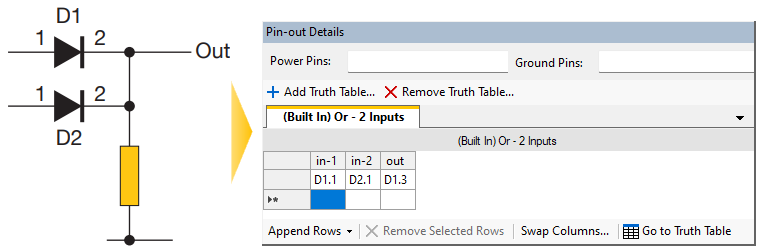
Figure 39: Creating a Logic Definition for a Diode OR with Separate Diodes
Having categorised D1 in this way, the system now knows how to control the Out signal. However, it still remains to categorise D2 because leaving it uncategorised will prevent Connection Test driving the nets. D2 should therefore be categorised as Ignored, and a note added to its categorisation to explain why.
If you want the reported test coverage statistics to be accurate, it will now be necessary to modify the coverage achieved by D2 to show it is being functionally tested. This is done in the Test Coverage screen by adding the pins in the Functional Tests tab.
Categorising Other Diodes
ESD diodes and similar protection devices with one end connected to power or ground should be categorised as Ignored because they have no impact on testing.
XJTAG v4.3.0