Constant Pins Screen

This screen allows the user to define pins — and by extension the nets to which they are connected — that must remain in a constant state during the connection test. The values set will also be the default values set to the nets when the test system is started or a Safe bitstream is applied.
There are four reasons for wanting to designate a pin as 'constant'.
- To keep the board in a safe state (prevent contention).
- To ensure the test system is not disrupted by a test (e.g. the connection test driving a reset pin).
- To exclude a pin (and therefore the net that it is on) from the Connection Test.
- To inform XJTAG of the expected state of a pin, to be checked during the connection test and in order to setup logic in the circuit.
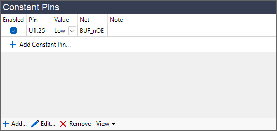
Constant pins can be enabled or disabled from this screen by checking or unchecking the checkbox in the Enabled column. Disabling this option will stop the pin from being held constant without removing the pin from the screen.
A constant pin can have one of 6 values:
- Low - XJTAG drives the net low.
- High - XJTAG drives the net high.
- IsLow - Something else is driving the net low and connection test should not drive it.
- IsHigh - Something else is driving the net high.
- IsDriven - Something else is driving the net. Although the level is unknown or varying XJTAG may still read and analyse this net.
- Excluded - this pin is driven, and XJTAG should not drive this net (and will exclude it from analysis) during Connection Test.
N.B. If your circuit uses 1149.6 testing, then on a net with a coupling capacitor defined, a constant value of Excluded will be observed during both AC and DC parts of the connection test, but values of High and Low can only be observed during DC tests due to the way in which the 1149.6 standard works.
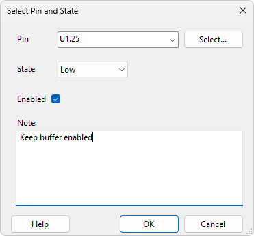
The  Add... button opens a dialog in which a pin from the circuit can be chosen and its constant value specified.
The  Add Device... button allows the user to set all pins on a particular
device as constant pins. Clicking the button launches a pop-up window to specify a device in the circuit and a value for the pins on that device.
Add Device... button allows the user to set all pins on a particular
device as constant pins. Clicking the button launches a pop-up window to specify a device in the circuit and a value for the pins on that device.
The  Edit... button allows the constant pin properties to be changed for the selected pins within the Constant Pins list.
Click  Remove to remove currently selected pins from the Constant Pins list.
Click  Reset to revert any changes made to the constant pins during the session, restoring the constant pins to those specified in the pack file.
The View drop-down button allows you to view the pin in various ways: in the Explorer window, the Layout Viewer, if available, the Schematic Viewer, if available, and on the Analyser Screen, if the pin is on a JTAG device.
XJTAG v4.3.0