Logic Definition Document
Clicking a logic definition in the Navigator will open that definition as a new document.
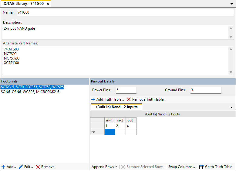
A logic definition contains some identifying elements, and one or more footprints:
Identifiers
These help you choose the correct logic to use.
- Name: The name for the logic, e.g. 741G00. This should be the type of logic.
- Description: A description of the logic type. This helps find the correct part.
-
Alternate Part Names: Alternative names for the logic that should define the full part names for this logic. Each is treated as a "contains", i.e. when entering text into the Navigator's Search Name text box a definition is a match if the alternate part name is contained within the text.
They can contain wildcards, which match zero or more characters, and use the same syntax as the Simple Patterns used by net and device categories.
Footprints
Footprints define the logic. Each corresponds to a physical type of component. They may vary with respect to pin layout and names for pins.
Several footprints may share the same logic definition – these are shown as a single entry.
Clicking on a footprint will show its pin-out. The power and ground pins are displayed along with a set of tabbed documents that show the gates of the device, grouped by the truth table used. Multiple footprints may share a pin-out.
In the example above there is one truth table used, which represents a NAND gate with 2 inputs. Each line inside the tabbed document represents one gate which uses the truth table, and the numbers in the table specify the pin number on the logic device.
The logic definition in the example above therefore has one logic gate on it, a NAND gate where pins 1 and 2 are inputs and 4 is the output.
Normally the pin-out will specify pins using just a number – this number then applies to the pin of this number on any device which has been categorised using this logic footprint. It is possible to create a logic gate which spans multiple physical devices by putting full pin references (e.g. IC8.4) into the pin-out table. This can be used to construct a logic gate which spans a group of devices, such as logic created from discrete diodes, but note that a footprint defined like this will only be applicable to one specific instance in your design.
-
Click
 Add... at the bottom of the Footprints list to create a new footprint:
Check Footprint covers all pin-out variations if this will cover all pin-out variations. It will show on the Footprints section as "default".
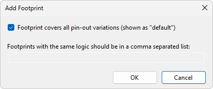
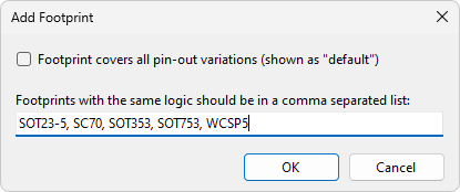
Uncheck it if you are defining one, or a set, of pin-outs:
- Click
 Edit... to alter the set of footprints that use a pin-out.
 - Click
 Remove to delete the selected footprint.
When a footprint has been selected, the truth tables used by that footprint are shown as tabbed documents.
See Entering Data into Logic Tables for help on how to modify data within a footprint.
- Click
 Go to Truth Table to open the definition for the selected truth table in a new window.
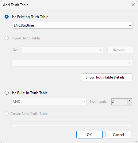
 - Click Add Truth Table... to use a different truth table:
- Check Use Existing Truth Table to use one of the truth tables defined in the LDD file.
- Check Import Truth Table to copy a truth table from another LDD file into this LDD file. This can be used to copy truth tables from the XJTAG Library for example.
- If either of the above options are selected, then click Show Truth Table Details... to view the truth table.
- Check Use Built-In Truth Table to use one of the truth tables automatically defined by XJTAG. These are, AND, OR, NAND and NOR. The No. Inputs control chooses the number of inputs the truth table will have. For example, selecting AND and 2 inputs will create a truth table with 2 inputs, "in-1" and "in-2", and 1 output, "out".
- Check Create New Truth Table to create a new truth table in the LDD file.
- Click Remove Truth Table... to stop using a truth table:
XJTAG v4.3.0