Test Reset Sequences for Subchains
XJTAG runs a Test Reset sequence, whenever the subchain it applies to is initialised or reinitialised, to put its devices into JTAG mode. However, the sequences are slightly different between dynamic and non-dynamic chains. If you have not explicitly created a Test Reset sequence for your subchain then XJTAG will use its Built-In or Built-In (nTRST) sequence (depending whether the chain uses an nTRST signal) which will work in the majority of cases.
For non-dynamic chains, a Validate process of counting the devices in the subchain, reading ID codes, and running Autoskew is always performed at the end of the sequence (although not shown explicitly in the sequence diagram). However, that is a problem if you want to set up pins during initialisation because the Validate process takes the devices out of EXTEST mode and therefore removes any pin settings that had been applied earlier in the sequence. As an example, if one subchain is being used to activate the board's power rails or to control a device's reset pin, those output pin settings would lose their values when Validate was performed.
To stop this happening, when you define a custom Test Reset sequence in a dynamic chains project, the Validate process can be inserted at any point in the sequence instead of having to be at the end. This allows pin values to be set after the chain validation has taken place. For dynamic chains, Validate is a step you need to explicitly add to a sequence.
- If a subchain is set to use a built-in reset sequence, this will always include a Validate step when dynamic chains are in use. However if you are creating your own sequence you must add it manually.
It should also be noted that the Validate process differs between dynamic and non-dynamic chains. When using non-dynamic chains a TMS reset is applied between each step of loading the Bypass register, counting the devices, reading their ID codes, and loading the Bypass register again ready to run Autoskew. However, the reset is only applied once in a dynamic chain. For dynamic chains, the Validate process consists of applying a TMS reset followed by reading the ID codes, loading the Bypass register, counting the devices, running AutoSkew, and finally selecting PRELOAD and loading the Safe bitstream.
The system is therefore expecting all devices in the subchain to have been left in PRELOAD with the Safe bitstream loaded after the subchain's Test Reset sequence has completed (unless a SAFE statement has been used in the sequence, in which case that particular device will be in EXTEST). Therefore, if Validate is not the final step, and JTAG scans occur after it in the subchain's Test Reset sequence, you must ensure all devices in that subchain are returned to PRELOAD (or EXTEST) with the Safe bitstream loaded at the end of the sequence.
When all the subchains' Test Reset sequences are complete, the system will issue the EXTEST instruction to all subchains because it wants all devices to enter EXTEST mode simultaneously.
Example: One JTAG Device Controlling the Power to Another
Consider the circuit shown in Figure 12, where JTAG device U1 controls the supply rail for another JTAG device, U2. To initialise U2's subchain, the subchain for U1 must first be initialised so that U1 can enable the power supply. Such outputs are defined by Constant Pins and/or Disable Values, and are set by applying a safe bitstream to the U1 subchain. The order in which the steps are performed must ensure that U1 stays in EXTEST mode once those values have been set so that U2 will remain powered during testing.
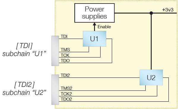
Figure 12: A Two-Chain Dynamic Configuration
The following series of events is therefore required to prepare this UUT for boundary scan testing:
- Run subchain U1 and enable power supplies:
- Initialise subchain U1.
- Check subchain U1 is working.
- Apply safe bitstream to U1 to set its output pins.
- Run subchain U2:
- Initialise subchain U2.
- Check subchain U2 is working.
There are two ways that this can be implemented, depending on whether you ever want to run the U2 subchain by itself during testing or whether both subchains will always run together. Both situations are described below.
Scenario 1: Both Subchains Always Run Together
If both subchains are always going to be run together during testing, the following steps can be followed:
- Create a Test Reset sequence for subchain U1 in which the safe bitstream is applied after the Validate step.
- If U2 needs a Test Reset sequence to be placed into boundary scan mode, create a Test Reset sequence for subchain U2.
- Define a profile containing both subchains and set the order in which they are initialised so that the U1 subchain is run first.
A suitable Test Reset Sequence for subchain U1 is represented by the diagram of Figure 13. Refer to JTAG Initialisation and Test Reset Sequences for guidance on creating a sequence.
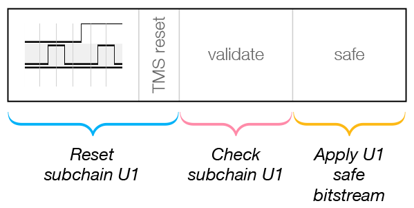
Figure 13: A Subchain Test Sequence Using Safe to Set Pin Values
The Validate step checks the subchain is working, reads any ID codes from devices in the subchain, counts devices, and then runs AutoSkew. The following Safe step applies that subchain's safe bitstream and puts U1 into EXTEST mode so that its output is set to enable power to U2. Because the Safe step occurs after the U1 subchain has been validated, the pin that it sets will still be in the correct state after completion of the subchain's Test Reset sequence.
In most cases, the built-in Test Reset sequence that will be created for the U2 subchain will be sufficient here. In this example, no Safe step is needed because U2 does not need to set up any pins. However if U2 requires a custom Test Reset sequence, that will also need to be created, and it will need to include a Validate step.
With the necessary Test Reset sequence(s) created, a profile can now be defined that includes both subchains, as described in Creating a Dynamic Chain Project above. The order in which the chains are initialised needs to be set so that the U1 subchain runs first to enable the power supply before the U2 subchain is run.
You may want to insert a delay between starting the subchains, for example to allow power supplies to settle after being enabled. This can be done by adding a Sleep step to the end of the Test Reset sequence for the U1 subchain.
Scenario 2: Option to Run Subchains in Isolation
A slightly different approach is required if you want the option of running the U2 subchain in isolation. In that situation, you still want the pin on U1 to be driven during the test so that the power supply remains enabled, but you want the ability to pause its subchain. To do this, the Test Reset sequence for U2 must also set up U1, which is achieved by making the Test Reset sequence for U2's subchain call the one for U1. This is represented by the diagram of Figure 14 below. Once the U1 subchain has been initialised to set the output pin, you will then be able to start testing with the U2-only profile, at which point the U1 subchain will no longer be clocked. Although the subchain is no longer running, U1's pin values will remain set.
In the Test Reset sequence for the U1 subchain, a Validate step checks the subchain is working and performs the AutoSkew. A Safe step then applies the safe bitstream to set U1's output.
You may also want to add a delay after setting U1's output pin, for example to allow power supplies to settle. This is done by introducing a Sleep step.
Once the called Test Reset sequence has completed, U1's subchain becomes paused and the Test Reset sequence for the U2 subchain continues by initialising its own subchain and then using a Validate step to check it is functioning.
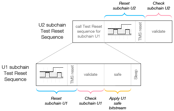
Figure 14: Dynamic Test Reset Sequences
Creating Test Rest Sequences for Subchains
A Test Reset sequence can be created once the related subchain has been defined. This is done on XJDeveloper's Pin Mapping screen, located within the list of screens under the Run and Deploy header:
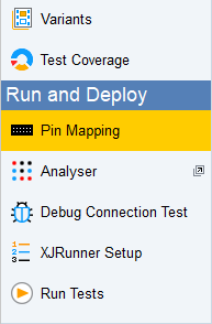
Figure 15: Accessing the Pin Mapping Screen
Test Reset sequences are created on the Test Reset Sequence tab as shown in Figure 16 below. Existing sequences are listed on the left, and the selected one will be shown as a diagram on the right.
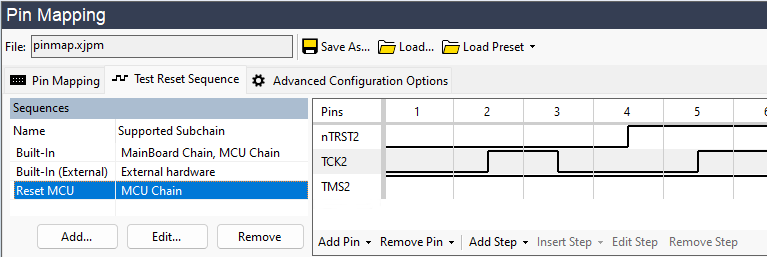
Figure 16: Creating a New Test Reset Sequence
To create a new Test Reset sequence, click the Add... button to open the New Sequence dialog box:
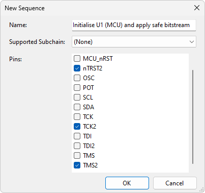
Figure 17: Starting to Create a New Test Reset Sequence
The dialog allows you to provide a meaningful name for this Test Reset sequence and use the dropdown menu to select the subchain to which it will be applied (Figure 17 shows a sequence being created for the subchain containing the MCU U1 in Figure 12, where U1 controls a power supply).
You can use the dialog to select which pins are needed to drive the reset sequence in the Pins list, although this can also be done from the reset sequence control itself if you forget to add any pins.
TDO pins are not listed in the Pins list - the reset sequence only shows pins driven by the XJLink.
Click OK to create a new entry in the list of Test Reset sequences, and the required steps can then be added. As was shown in Figure 14 above, the Test Reset sequence for the U1 subchain in our example needs the following steps in order:
- Perform a Test Reset on U1 by manipulating its JTAG signals and nTRST pin (typically accomplished using a Pulse nTRST step).
- Perform a TMS reset.
- Perform a Validate step to check the U1 subchain is functional.
- Apply the safe bitstream to set U1's pin values to enable the power supply.
- If required, include a Sleep step to add a delay after setting the pins.
When adding a reset sequence to a subchain, you may be prompted to update all profiles containing that subchain to use the new reset sequence. This may affect whether Automatic Configuration still considers the profile as automatically generated.
The necessary nTRST transitions and the TMS reset step are added in the same way as for standard chains (for details, refer to JTAG Initialisation and Test Reset Sequences in the user guide chapter on Setting up a Physical JTAG Chain ).
To add the step that checks the chain is functional, click Add Step below the diagram of the pin transitions and select Validate from the menu. It will then be shown in the Test Reset sequence diagram:
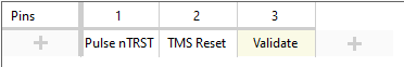
Figure 18: A Test Reset Sequence with a Validate Step
- A TMS Reset should be placed before the Validate step so that the system knows what state the subchain is in. When the system runs Validate, it expects the IDCODE instruction to be already loaded in the devices, which the TMS Reset will do.
The next step to add is the safe bitstream: click Add Step and select Safe from the menu. This is then added to the sequence. Because it has been placed after the Validate step, the pin values set by the safe bitstream will be maintained beyond the end of the Test Reset sequence. Note that the safe bitstream is not applied to all devices in the project, but only to those in the current subchain.
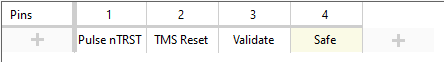
Figure 19: A Test Reset Sequence with a Safe Statement
- Executing a Safe step before all the chains have been initialised should only be considered with caution because it will cause pins to be driven while other devices are not in JTAG mode and may be operational, potentially causing contentions. A Safe step should therefore only be used in the Test Reset sequence if you need to drive specific pins before all the JTAG chains have been initialised (e.g. to enable a power supply required by another JTAG device, or to control a Reset pin to allow other subchains to be run). If you don't need to set pins during initialisation, you should leave the system to apply the safe bitstream automatically when it puts the subchains into EXTEST mode.
- Remember, also, that it's the whole device that is put into boundary scan mode rather than individual pins.
- If a Test Reset sequence does not include a Safe step, devices in the subchain will be put into PRELOAD mode with the safe bitstream loaded as part of the Validate step. They will remain in that mode until all the Test Resets have been completed. Once all the initialisations have been done, the system will put all devices into EXTEST mode simultaneously.
- If you need to control pins to enable several power supplies in a specific order rather than switching them on simultaneously, it will be necessary for the Test Reset sequence to call XJEase functions containing Default Overrides rather than setting them with a Safe step. If Safe statements were used to switch on the power supplies, all the Enables would be set on the same TCK edge, which would not allow for sequencing the supply rails. Instead, a Safe step should be used first to initialise the chain with all the power supplies off, followed by default overrides to turn on the power supplies in the required order with suitable timing.
If required, a delay can be placed at the end of this Test Reset sequence by adding a Sleep step.
One Test Reset Sequence Calling Another
Now that the Test Reset sequence for the device controlling the power supplies has been created, it can be called from another Test Reset sequence if required. In our example, where U2's power supply is controlled by U1, a Test Reset sequence for the U2 subchain can be defined, made up of the following steps:
- Call the Test Reset sequence that initialises U1 and applies its safe bitstream.
- Pause U1's TAP signals and switch to using U2's TAP group instead.
- Perform a TMS reset on the U2 subchain.
- Apply a Validate step to check the U2 subchain is functional.
As before, click Add... to create a new Test Reset sequence; provide a meaningful name and select the required subchain. The individual steps for this sequence can now be added.
To make this Test Reset sequence call another one, either click Add Step at the bottom of the screen or use the + button indicated in figure 20, and choose Select Subchain from the menu:
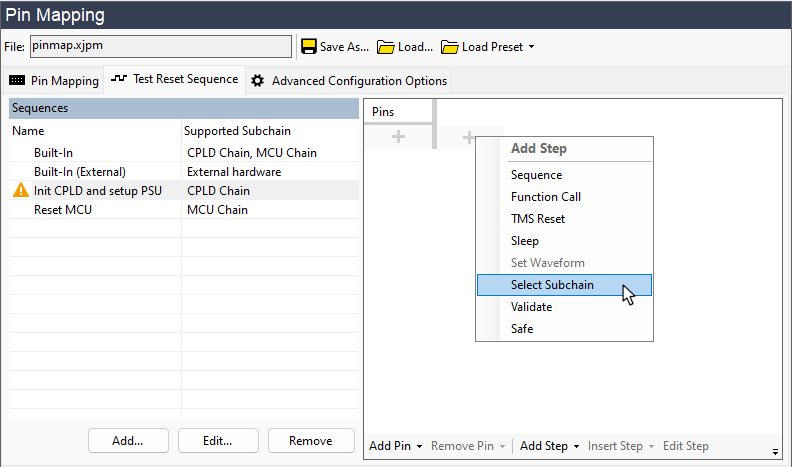
Figure 20: Adding Another Chain's Test Reset Sequence
Select the subchain to be run (and the reset sequence to be used to do so) using the drop-down menus in the subsequent dialog box. This step will now be shown in the sequence diagram:
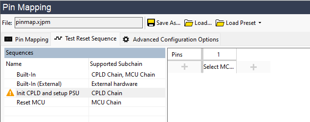
Figure 21: Initialising Another Subchain from a Test Reset Sequence
This step will call the sequence that runs on U1's subchain, the result of which is that the pin values will be applied to enable the power supply.
There is a warning icon shown against this TRST sequence because the sequence does not yet contain a Validate step.
- Once the call to the other Test Reset sequence has been completed, the TAP signals for that subchain will stop changing, and the subchain will remain paused without its chain running.
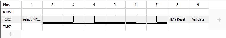
The remaining steps of a TMS Reset and a Validate step can now be added as before, with or without the JTAG pins being manipulated, depending on what is required:
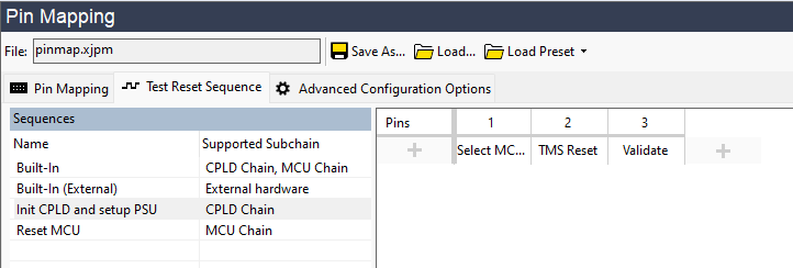
Figure 22: Complete Test Reset Sequence with a Call to Another Reset Sequence
If a device has an nTRST pin, the Test Reset sequence should set that pin (in the waveform or by using a Pulse nTRST step) after calling the other subchain's Test Reset sequence but before the TMS Reset. This is necessary to put the device into boundary scan mode ahead of applying the TMS Reset.
Using XJEase Functions in a Test Reset Sequence
It is also possible to call global XJEase functions that reside in circuit code files. This can be useful if you want to control the order in which pins are set during initialisation or to do something more advanced. For example, you could use XJEase functions as part of setting up the board to generate I2C commands to control a device such as a PMIC. Such functions can be inserted into the Test Reset sequence by clicking Add Step and selecting Function Call from the dropdown menu. This opens the Select XJEase Function dialog that has a dropdown menu of available functions.
- A Test Reset sequence can only call XJEase functions that are in circuit code files. If you need to run a function that is in a test device file (e.g. to use an I2C function), it will first be necessary to create a function in a circuit code file that uses an XJEase CALL statement to call the function you want to run. Calling that circuit code function from your sequence will then execute the one in the test device file.
XJTAG v4.3.0