Connections
The Connections tab allows you to tell XJTAG that specific pins or devices are connected together, updating the circuit representation in your project and allowing tests to be run through the connections. This both allows you to test your entire system once it has been assembled and allows you to test any external connectors by using loopbacks.
XJTAG has two ways to define a connection, either device-to-device or pin-to-pin. When connecting two boards together, this will typically use a device-to-device connection, allowing all the pins on one connector to be connected to all the pins on another. When describing a wire mod, a pin-to-pin connection would be used to link specific pins on the two devices.
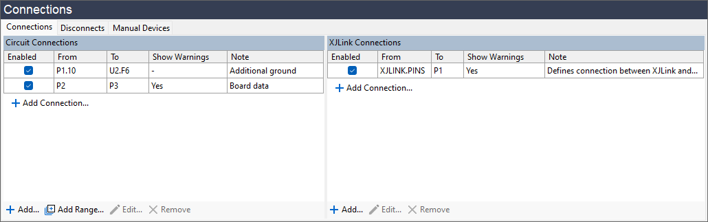
Figure 2: Connections tab
The connections which have been added to the project will be shown on the Connections tab, along with information about whether they're enabled and the user-created description. This Note is entirely cosmetic, however we recommend that you add one as it will make it much easier for you to tell why a connection was made when you return to the project later.
Connections between devices or boards are shown in the Circuit Connections list. Whereas connections between the UUT and the XJLink are shown under XJLink Connections.
To add a connection, either click  Add Connection... at the end of the appropriate list, or click the Add... button at the bottom of the tab. This will bring up the Add Connection dialog box:
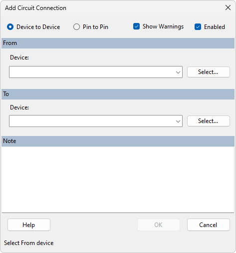
Figure 3: Add Connection dialog
From here, there are a number of ways that a connection can be configured.
- If a connection is made between two pins on the same device (e.g. as a loopback) the system will show a warning. Loopback connections using a single device are usually represented better with a passive device file.
Device-to-Device
If you select the Device to Device option at the top, XJDeveloper will link each pin of the devices, connecting pin 1 of the first device to pin 1 of the second, pin 2 to pin 2 and so on. This allows you to very quickly and easily configure a wide connection between two boards – a 100 pin connector is just as easy as a 4 pin. If the two devices have different numbers of pins, a warning will be displayed at the bottom of the dialog box, but the connection will still be made for all matching pin numbers.
To create this connection, either start typing the reference designator of the device in the From: box, then select from the list which appears, or click on the Select... button to open a list of all devices in your project. Repeat this with the To device, optionally add a descriptive Note in the bottom box, and then click OK to save it.
- We recommend adding notes to connections to help the understandability and maintainability of the project.
Pin-to-Pin
If you select the Pin to Pin option, you can create a connection which links any two individual pins in your circuit. This is achieved very similarly to the device option, by typing the reference designator of the device into the box, followed by a dot and the pin number. As before, a popup will appear as you type to allow you to select an option. Also as before, you can also click Select... to open the dialogue box and choose a component from the list, but now you can select the specific pin as well.
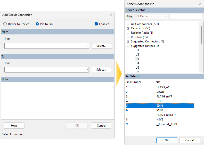
Figure 4: Selecting a specific pin
Next, select the other end of the connection in the same way, give the connection a Note to make it easy to identify in the future and click OK to save the new entry.
XJLink Connections
So far, we've talked about making connections on the same board or between boards. XJLink connections specify a connection between the JTAG controller and the board(s). Defining this connectivity will allow the system to check the pin mapping definition against the circuit and highlight any JTAG connectivity issues. It also allows any pins which aren't used for the JTAG signals to be used as additional points of access to your board. These extra connections can be used automatically as required in both the connection test and any device tests, extending test coverage.
When using XJLink pins as additional points of non-JTAG access, they must first be configured in the Pin Mapping screen. Select the pin you wish to use and then set its type to PIO. This tells XJTAG that this is a Programmable I/O pin and so can be used to set or read the state of nets on the board. The PIO Name should also be set – this is entirely cosmetic, but allows you to identify the pin more easily wherever it's used.
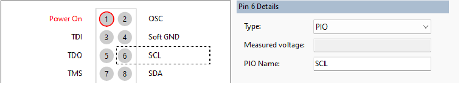
Figure 5: Setting a pin to be Programmable I/O
You can then use the Connections screen to define the connectivity between the XJLink and the circuit. From the screen, add a new XJLink connection. In the From section of the dialog, select the type of XJLink you are using and the connector from which to make the connection. If you are using an XJLink2, PINS will be automatically selected as there is only one connector. If you have Pin to Pin selected then you will be able to select a specific XJLink pin from the dropdown. The pin type or PIO Name will show after the pin number to help find the correct pin:
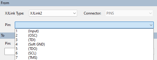
Figure 6: Connecting from XJLink2
- Typically, the connection to the XJLink will use pin-to-pin because the board is unlikely to have connectors that exactly match the connectors on the XJLink.
Now select the location on your board that this pin is connected to in the To field. XJDeveloper will handle the rest, including working out improved access, test patterns and coverage. As before, click OK to save the new entry.
- Adding any connection from the XJLink will cause all PIO pins to be used during the connection test, so ensure all pin connections are correctly defined.
A connection to a PIO pin will be visible in Explorer with the label NJTE (non-JTAG test equipment), which allows you to confirm that the connection has been made properly inside the software.
- When connecting to the JTAG header, we recommend using a ribbon cable if possible. See Setting up the JTAG Chain for more information.
Add Range
The  Add Range... button in the Connections tab allows you to add multiple connections on sequential pins in a single step. Whilst a device-to-device connection allows you to link two devices with pin 1 to 1, 2 to 2, etc, Add Range... allows you to use any series of pins, incrementing or decrementing by one each time, without the pin numbers having to match. For example, either of the following sets of connections are possible between two devices P1 and P2:
| P1 | P2 | |
|---|---|---|
| 1 | to | 7 |
| 2 | to | 8 |
| 3 | to | 9 |
| 4 | to | 10 |
| P1 | P2 | |
|---|---|---|
| 3 | to | 5 |
| 4 | to | 4 |
| 5 | to | 3 |
| 6 | to | 2 |
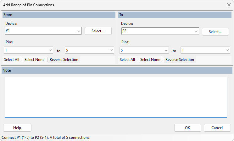
Figure 7: Adding Connections to a range of pins
As before, select the devices that you want to link From and To, then select the pin range. The number of pins in each range must match, or an error will be displayed. Add a note for future reference and then click OK to save. Each pair of connected pins will be displayed separately in the table – Add Range... allows you to create a number of entries quickly and easily as a single action, but they will be saved and displayed as individual connections, unlike device-to-device connections.
As an advanced option, if you need to create a more complex pattern than the Add Range of Pin Connections dialog supports, such as many non-sequential pin groups, it is possible with care to produce correctly formatted entries in a separate text editor and copy this directly into the project files. For connections between devices on a single board, this would be done in the relevant board file, by default this will be called Board-<boardname>.xje where <boardname> is the name of your board on the Boards screen. The entries should be added in the CONNECTION LIST section in the following format:
	CONNECT PINS P1.1 TO P2.1;
	CONNECT DEVICE P1 TO P2;
For connections between boards, this should be done in the project level .xje file, which will have the same name as the project. Again, the entry should be added to the CONNECTION LIST section, but this time must include the board names:
CONNECT DEVICE MainBoard.P1 TO PowerModule.P1;
- Ensure you have backed up your project files before making any changes to them outside of XJDeveloper, because if you introduce a syntax error it could prevent the project from loading.
Other Controls
The table of configured connections has an Enabled column. This allows you to easily disable a connection from affecting the tests, without having to  Remove it, by simply unticking the box in the column.
Finally, there is a Show Warnings column allowing you to disable warnings which have been reviewed and determined to be expected, such as missing pins on device-to-device connections. This can be changed by right clicking on the row and ticking/unticking Show Warnings.
XJTAG v4.3.0