XJLink2
Bank Settings
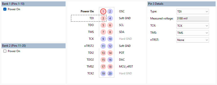
The XJLink2 connector is split into 2 banks: bank 1 (pins 1 to 10) and bank 2 (pins 11 to 20). The settings for bank 1 can be modified in the Bank 1 (Pins 1-10) panel on the top left. The settings for bank 2 can be modified in the Bank 2 (Pins 11-20) panel on the bottom left.
Bank Power Options
Power can be supplied to the hardware by either an external power supply or by the XJLink2 through its USB connection.
The power is off by default, which means the hardware expects to be powered by an external power supply.
USB power can be applied via pin 1 for bank 1 or pin 11 for bank 2. You can do this by selecting Power On from the bank's settings panel or by double-clicking on the relevant pin on the visual representation of the XJLink2 connector.
N.B. Applying power to a board that is already powered externally may damage the USB interface or the board.
Bank Voltage Options
These options are only visible when the Use advanced settings checkbox is enabled.
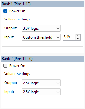
The voltage logic level for output pins can be set per bank. A preset value can be chosen via the Output dropdown menu in the bank settings. Alternatively, a custom value can be used by picking Custom level from the respective dropdown menu.
The voltage can also be set for input pins in each bank. They can be set to a preset logic level via the Input dropdown menus. A custom threshold can be set by selecting Custom threshold.
Note: Custom input voltages are threshold values, so anything above that value will be deemed high. Input voltages selected from the preset values are logic levels which are designed to operate with digital signals outputting at the specified voltage (meaning the threshold will be much lower). So the preset 2.5 V logic level may in practice recognise values as low as 1.1 V being high.
Note also that input pins can have their input voltage set to match the bank setting or to one of the preset voltages on a per-pin basis.
Advanced Pin Settings
These options are only visible when the Use advanced settings checkbox is enabled.
Slew Rate
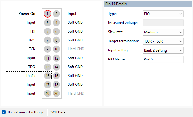
The Slew rate for an output pin can be set to Fast, Medium or Slow. In general, this will not need to be altered.
Target Termination
Specifying the termination of the signal will allow an appropriate drive strength to be selected automatically. Higher termination value ranges (with None being the highest) will result in lower drive strength because less current is required to achieve the same voltage drop across the load on the driven line.
Input Voltage
The input voltage for an input pin can be independently set to be one of the standard values (1.2 V, 1.5 V, 1.8 V, or 3.3 V) or to be the same as the appropriate bank's input voltage setting (see Bank Voltage Options).
XJTAG v4.3.0