Edit SPEA information
Choosing SPEA as the ICT Machine Type allows information for either a Flying Probe or Bed of Nails machine to be added. The machine type is determined automatically by the files imported from a Leonardo project.
There are several files exported from Leonardo which XJTAG can use to add information to a project:
- HwConf.txt: Contains details about the machine used in the Leonardo project. If using a Flying Probe machine, this file specifies whether it is a digital or analogue machine, and how many probes it has. If the machine is a Bed of Nails machine, this file specifies whether each of the channels is digital or analogue.
- PinList.txt: Can be used as the board netlist. If another netlist is used instead, PinList.txt is used to cross-reference pin names in the netlist with test points in TPList.txt.
- PartList.txt: Contains BOM information for the board. Any devices which are uncategorised in XJDeveloper and are marked in PartList.txt as 'Not Mounted' will automatically be categorised as Unfitted. If such a device is already categorised differently in XJDeveloper, a warning will be added.
- PPS.txt: Contains details about the power and ground nets on the board. When the SPEA information is imported, this will be used to automatically categorise power and ground nets where possible. Nets in the Zero Net field will be categorised as Ground; nets in the Supply Net field categorised as either Power if the value of the Pws VTT field is 'False', or as Termination Reference if the value of the Pws VTT field is 'True'. If this information conflicts with the existing categorisation of nets in the project, a warning will be added. Power, Ground and Termination Reference nets automatically categorised through PPS.txt are not available to be recategorised while the external hardware information is associated with the board.
- TPList.txt: Contains information about the testpoints available to the SPEA machine, including coordinates, voltage domains information, and accessibility information. The voltage domain for each test point is specified in the Net Class or Digital Class field of TPList.txt and will be used to determine high, low and threshold voltages for the test point.
There are two options for importing the required information from Leonardo:
- Select Leonardo project - Enter the base directory of the Leonardo project to use. This should be the directory which itself contains the PROGRAM\XJTAG subdirectory, and this is where XJDeveloper will search for the required files. This option defaults to the most recently opened project in Leonardo. If this option is selected, XJDeveloper requires the names of the files in the Leonardo project to match those above.
- Select Leonardo files - This allows each file to be selected independently. In this case, the filename does not necessarily have to match the corresponding file above, but the file extension must be the same. This makes it easy to change which version of a file is used for a particular board.
In each of these cases, all of the above Leonardo files must be provided (either contained in the PROGRAM\XJTAG directory, or specified manually) with the exception of PartList.txt, which is optional and will be used to add BOM information to the board if present.
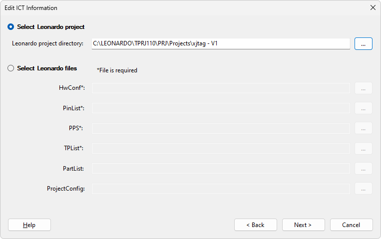
There is one further file which can be used in conjunction with the information from Leonardo, ProjectConfig.ini, which specifies the location of any probes which must remain fixed at a certain testpoint for the duration of testing. Typically this would be necessary when two probes are being used to provide power to the board, and must remain fixed at certain testpoints on the power and ground nets. This file is not exported from Leonardo, but will be automatically generated by XJTAG when SPEA information is added by referencing a Leonardo project, and saved in the PROGRAM\XJTAG directory alongside the other files. If the files are selected independently, the ProjectConfig.ini file will not be generated, but an existing file may be referenced in the same way as with the other files. The file should contain each probe which needs to be fixed, with the corresponding value being the testpoint number where the probe should be fixed. For example:
[POWER]
PROBE5=1205
PROBE6=948
In the example above, probe 5 is fixed at testpoint 1205, and probe 6 is fixed at testpoint 948. When using probes to power the board, it is preferable to choose probes on the bottom of the board to power the board so that they do not get in the way of the moving probes. When probes on the top side are fixed, careful selection of testpoints is required to avoid restricting the movement of other probes and preventing access to large parts of the board.
Click Next > to configure the voltage domains used by the SPEA machine.
Click < Back to re-select the type of external hardware to use.
XJTAG v4.2.5