Creating a New Variant
- The root project must already exist before a variant can be created, and should be fully categorised.
The process to create a variant is as follows:
- Create a root project.
- Define the device variations. This can be done using the wizard or by following a manual process.
- Define variations to configuration values, constant pins, and Connections & Disconnects.
- It is not possible to have a variant of a variant – variations can only be from the root project. However, it is possible to copy a collection of individual variations from one variant to another.
To create a variant, open the root project and go to XJDeveloper's Variants screen:
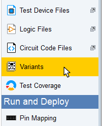
Figure 1: Accessing the Variants Screen
Click Add... at the bottom left of the  Variants screen to open the Add Variant dialog box (Figure 2). The board(s) in the root project will be listed. To continue, provide a name for the new variant.
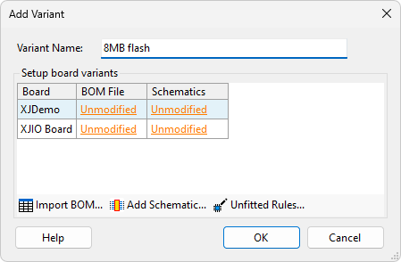
Figure 2: Creating a New Variant in the Add Variant Dialog
If you have a BOM file for the variant that identifies its differences to the root, the Variant Setup Wizard can be used. This provides the quickest route to setting up the variant. If no BOM file is available, the wizard cannot be used, and a manual setup will be required. These two methods are described in the following sections.
- Adding a BOM for the variant simplifies project creation because it allows the Variants wizard to make suggestions on what has been changed.
- If the root project is altered by changing a device after variants have been created, XJDeveloper will attempt to update the variants automatically.
- Any errors related to a variant are only shown when the variant is loaded.
- In a multi-board project, it is not possible for a variation to remove a board. If this is necessary, the approach is to remove the connections between the boards.
- If it's important to have accurate test coverage statistics, it will be necessary to export the variant as a standalone project and open it within XJDeveloper after it's been created. This is because the test coverage reported is always that of the root project.
- If revisions are applied to the root project after variations have been created, the variants will be removed and must therefore be recreated afterwards.
- Devices that were manually added to the root project using XJDeveloper's
 Connections screen cannot be varied.
Setting Up a Variant Using the Wizard
To use the Variant Setup Wizard, click Import BOM... and select the relevant file:
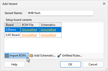
Figure 3: Importing a BOM allows the Variant Setup Wizard to be Used
Once the file has been selected, the Import BOM dialog will open. This is similar to the one used when entering board data for any other project. Assign the columns of BOM data from the file to XJDeveloper's data types.
The Root BOM... button (Figure 4 below) can be used to display the data that was imported for the root project in a separate window. This allows you to see how BOM information was mapped to the different data types for the root project.
- The wizard is most effective when the variant's BOM data is mapped to XJDeveloper's data types in the same way that the root project was mapped. Viewing the root BOM is therefore helpful because it allows you to see how data was mapped to the different data types in the original.
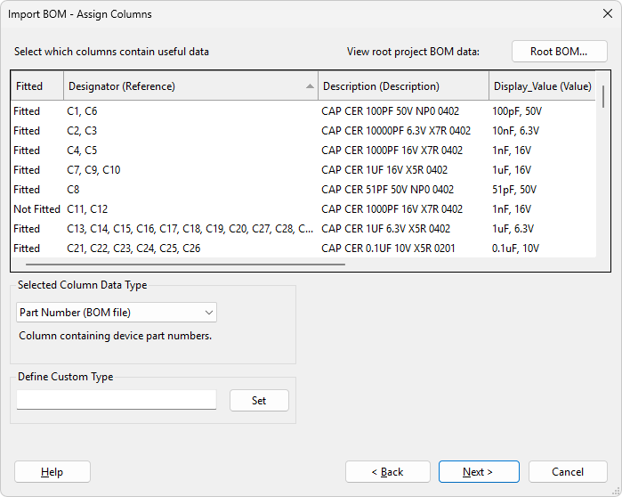
Figure 4: Viewing the Root BOM to see How Data Was Mapped to Different Data Types
Once the data has been imported, you will be returned to the Add Variant dialog. The variant BOM will now be listed (Figure 5). An item unchanged from the root project is marked as Unmodified:
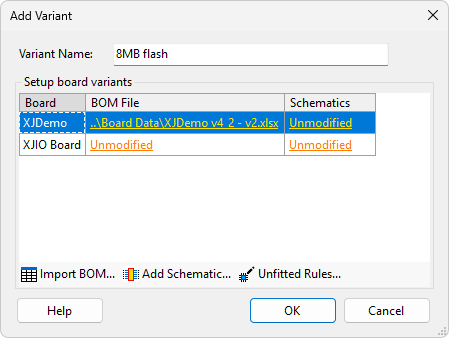
Figure 5: The Add Variant Dialog with a BOM File Entered
If a schematic file is available for the variant, it can be added by clicking Add Schematic...
If unfitted devices are identified in the variant's BOM file in a different way to how they're shown in the root board's BOM, you may need to set up different rules for the variant. Click Unfitted Rules... to define how XJDeveloper is to identify unfitted devices in the variant.
Once the BOM(s) and any schematic(s) have been imported and the unfitted rules changed for the variant if necessary, click OK. The Variant Setup Wizard will now be launched automatically and will suggest what has been changed in this variant.
The wizard will take you through a number of steps to categorise the devices that have changed as described below. Up to five steps will be shown, depending on what types of changes exist in the project.
-
- Unfitted suggestions
- This step lists devices that were fitted in the root project but are identified as unfitted in the variant's BOM. It will also include any devices that the variant's BOM indicates are unfitted, but which were uncategorised in the root project.
-
- Resistor suggestions
- Devices that XJDeveloper believes are resistors that were unfitted in the root project but appear to be fitted in the variant are listed in this step.
-
- Capacitor suggestions
- Devices that XJDeveloper believes are capacitors that were unfitted in the root project but appear to be fitted in the variant are listed in this step.
-
- Fitted suggestions
- Any other devices that were unfitted in the root project but appear to be fitted in the variant are listed in this step.
-
- Value change suggestions
- This step lists devices that were fitted in the root project but have a part number or value that is different in the variant's BOM.
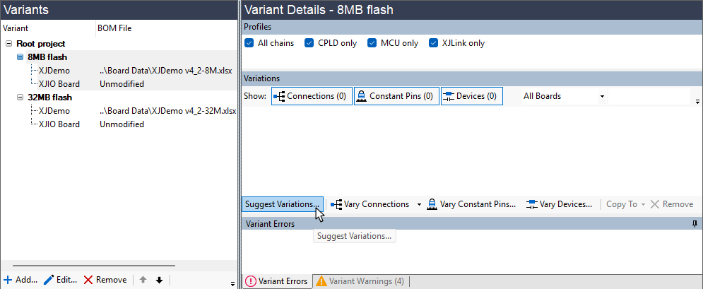
- The Variant Setup Wizard can be opened at any time by clicking Suggest Variations in the Variants screen. The required variant must be selected in the left pane.
The process is to work through the different steps. For each device that has changed, you can either accept XJDeveloper's suggested categorisation, select a different category yourself, or skip categorising that particular device.
- Skipping an accessible device can result in Connection Test errors for the variant. Before completing a project you should make sure that no accessible devices have been skipped, by making sure the Show Skipped checkbox at the top of the wizard is ticked, and then if any skipped devices are shown clicking the Undo button for each skipped device, and then configuring them as described below.
Each step has a similar interface. An example for proposed resistor changes is shown in Figure 6 below. When XJDeveloper is able to suggest how to categorise a new or changed device, clicking Accept will apply the suggested categorisation.
If XJDeveloper doesn't have a proposal for the device's categorisation, or you want to categorise it differently to the suggestion, click Configure. This will open the Assign Device dialog, in which you can select a category for the device. The method is similar to when categorising devices on the  Categorise Devices screen.
To ignore a suggestion, click Skip.
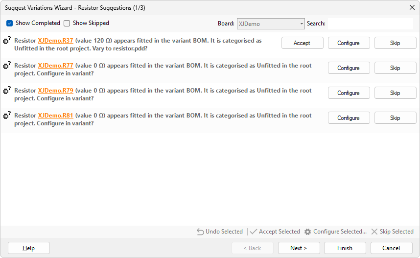
Figure 6: The Wizard's Suggested Changes
To check how a device is being used in the circuit, right-click on its reference and select either Show in Schematic Viewer or Show in Explorer.
- Explorer will show access based on the root's default profile.
Right-clicking on the message rather than the device and selecting Show in Schematic Viewer will open schematics for both the root project and the variant. The variant will be identified by a yellow banner at the top. This allows a comparison of the device between the two projects. Similarly, opening Explorer in this way will open two Explorer windows, one for each.
As the devices are categorised, the variations will be moved to the bottom of the list. Completed and skipped variations are identified as shown in Figure 7 below. If a mistake has been made, click Undo and recategorise the device. You can also use the two checkboxes at the top of the wizard to show or hide completed and/or skipped devices. This may make the wizard clearer when there are a lot of variations being suggested.
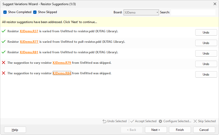
Figure 7: Completed and Skipped Variation Suggestions are Shown on the Screen
Once you have completed a step, you can move to the following one by clicking Next >.
- You can move between the different steps without having completed the current one by using Next > and < Back.
If devices change from being unfitted in the root to being fitted in the variant, one of the steps will be Fitted Suggestions. The interface for this step has a BOM Data dropdown menu (Figure 8) that can be used to include information from the BOM in the displayed messages. The chosen data will be added in parentheses after each device's reference designator.
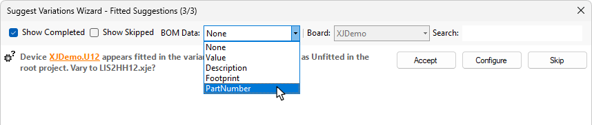
Figure 8: Displaying Additional BOM Data During the Fitted Suggestions Step
After all the steps have been worked through and all devices categorised, click Finish.
Having completed the steps in the wizard, the devices in the variant project will have been categorised. However, there may still be changes required to Configuration variables as well as Constant pins and Connections, and these need to be performed manually. The processes for these are described later in this guide.
Once fully completed, the variant project(s) should be checked for errors and warnings – refer to the section below on Checking Variants for Warnings & Errors.
Setting up a Variant Manually
If you do not have a BOM file for the build variant, the wizard cannot be used, but a variant can be created manually instead. On the Variants screen, click Add... to open the Add Variant dialog. Provide a name and, if a schematic is available, browse to it by clicking Add Schematic...
Click OK, and you will be returned to the Variants screen, with the newly created variant listed in the left pane as shown below.
The next step is to input details of the device variations: select the variant in the top left pane (1) and then click Vary Devices (2).
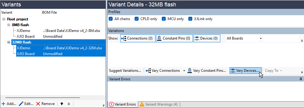
Figure 9: Manually Creating a Variant
This will open the Vary Devices dialog, in which the differences to the root project can be entered:
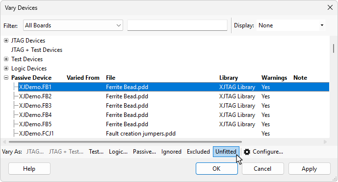
Figure 10: Manually Defining Variations
The dialog works in a similar way to the Categorise Devices screen: select the device to vary in the lists (1) and click the button for the category required in the variant project (2). Text can be entered into the Filter: box (3) to make locating the device easier. To help identify the different components, additional information on the root project's device such as part number or value can be displayed by using the dropdown Display: menu (4).
Devices that were categorised in the root project are grouped according to that original categorisation. Devices that were inaccessible in the root but can now be accessed in the variant will be listed in the Accessible Uncategorised Devices group at the bottom of the dialog.
- If a variant has a JTAG device with more I/O than was present in the root project, devices connected to the additional I/O will appear in the Accessible Uncategorised Devices group.
- It is not possible to add a new JTAG device as a variation: all JTAG devices must be present in the root project. However, a JTAG device can be changed to a different part with a different BSDL file (e.g. a version of the device with a larger memory) provided its TDI and TDO pins remain the same.
- It is always necessary to have a JTAG chain that can run. If you have two JTAG devices in parallel, with 0 Ω resistors to determine which is in-circuit for different variants, please contact XJTAG support for advice on how to ensure the chain in the root project is valid.
- If a JTAG device becomes unfitted in a variant, XJDeveloper will automatically add a Connection between the TDI and TDO pins of that device in order to make sure the JTAG chain remains functional.
- It is only possible to vary devices that are categorised in the root project, or which have newly become accessible due to a variation. If a device that was originally uncategorised is assigned a category in the variant (e.g. categorised as Unfitted to improve the accuracy of the test coverage statistics), the system will automatically categorise the device as Excluded in the root project. .
When a model file needs to be assigned to a device, clicking the required category button will open the Configure Device As dialog. The procedure is then the same as when categorising devices in the Categorise Devices screen.
Once a device has been varied, it will remain in the Vary Devices dialog but will be moved to its new group and will be marked in orange. For example, a device that was categorised as Passive in the root project but as Unfitted in the variant will be moved to the list of unfitted devices:
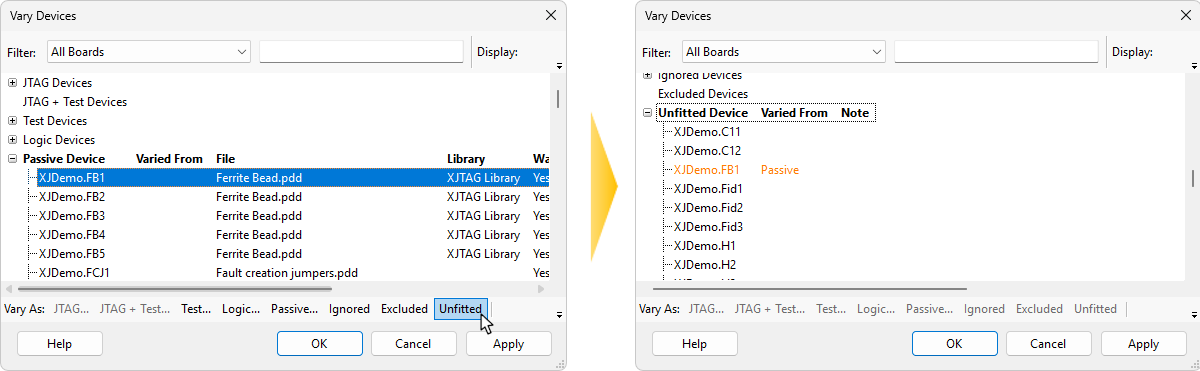
Figure 11: Varying a Device Moves it to its New Group
Click OK once all the variations have been defined. They will now be displayed in the Variant Details pane:
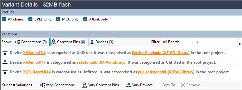
Figure 12: Entered Variations are Shown in the Variant Details Pane
It is important to appreciate that the changes are only applied to the project when OK is clicked in the Vary Devices dialog; JTAG access is consequently only updated at that point. If varying a device results in additional devices becoming accessible, the system will therefore only know about them once OK has been clicked. It is therefore essential after using the Vary Devices dialog and clicking OK to click Vary Devices... again, and to check the Accessible Uncategorised Devices group for any additional devices. Repeat this process until devices stop appearing in that list.
If you've made a mistake, a variation can be cancelled by selecting it and clicking Remove below the list of variations.
- If a Test device is selected, it can be changed to a different device in the variant project but it cannot be changed to a JTAG device because JTAG devices cannot be added to a variant project. All JTAG devices must have been categorised as such in the root project.
XJTAG v4.3.0