XJLink-PF series
Connector Map
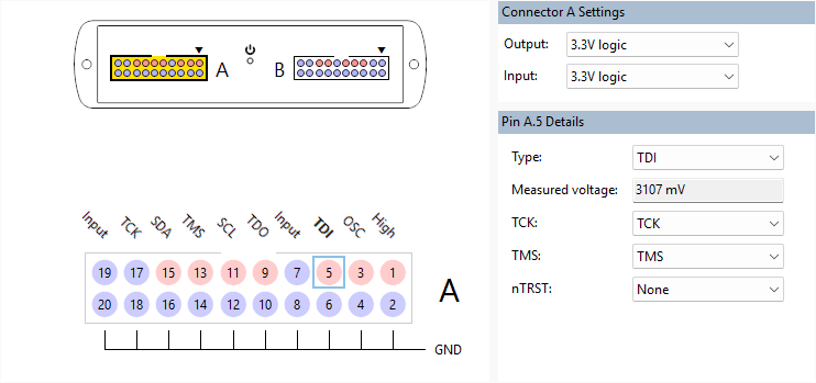
XJLink-PF series controllers have multiple connectors, each with 20 pins. The main graphical view only displays one connector at a time, and the selected connector can be changed using the XJLink connector map above. Changing the selected connector also updates the Connector Settings panel on the right.
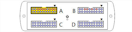
Right-clicking on a connector in the connector map opens a context menu with the following options:
- Move To - moves this connector's pin assignments onto the chosen connector. The original connector will have all its pins set to Input.
- Swap With - swaps this connector's pin assignments with those of the chosen connector.
- Copy To - duplicates this connector's pin assignments as closely as possible on the chosen connector. Note that some changes will be made where pin settings cannot be identical across multiple pins; for example, TAP pins will have their index incremented to the next available index, and PIO pins will have their name modified.
- Reset to Safe - sets all pins on this connector to Input.
Voltage Settings
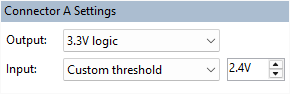
The voltage logic level for output pins can be set per connector using the Connector Settings panel in the top right. A preset value can be chosen via the Output dropdown menu, or a custom value can be used by picking Custom level from the respective dropdown menu.
The voltage can also be set for input pins in each connector. They can be set to a preset logic level via the Input dropdown menu. A custom threshold can be set by selecting Custom threshold.
Input pins can alternatively have their input voltage set to match the connector setting or to one of the preset voltages on a per-pin basis. This is done by selecting a pin and using the Input voltage dropdown menu in the Pin Details panel on the right.
Note: Custom input voltages are threshold values, so anything above that value will be deemed high. Input voltages selected from the preset values are logic levels which are designed to operate with digital signals outputting at the specified voltage (meaning the threshold will be much lower). So the preset 2.5 V logic level may in practice recognise values as low as 1.1 V being high.
XJTAG v4.3.0