Constant pins
This page specifies pins which should be kept at a constant value. These constant values are applied during the Learn Connections process and for the Connection Test.
Some pins will break the JTAG chain if driven to a particular value - for example, if a chip has an active high reset pin, this should be set to a constant value of low. These should always be set before running the Learn Connections tool.
It is best to set constant pins to disable the non-JTAG devices on the board where possible. If not possible, the output pins of that device should be set to a constant value of Excluded so that we do not drive against them.
For the demo board, for example we can disable the flash (U3) by driving its nCS pin high. In this case because we have the schematic we can use the schematic to see that this can be achieved by setting U2.D4 to drive High and disabling the logic (U8) that can also drive the net, which in turn can be achieved by setting U2.H5 also to high, and U1.25 to Excluded so as not to conflict with U2.H5. Another example is the accelerometer (U12) which cannot be disabled, and therefore its interrupt pins 11 and 12 must be ignored - these are connected to U1.63 and U2.H6 which must therefore be set to a constant value of Excluded.
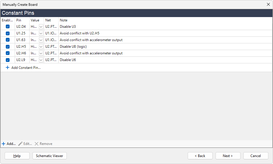
In summary, from the schematic provided for the demo board, we can see that we need to set:
- U2.D4 to High in order to disable U3 (flash)
- U2.H5 to High in order to disable U8 (logic)
- U1.25 to Excluded so as not to conflict with the output of U2.H5
- U2.L9 to High to disable U6 (SRAM)
- U2.H6 to Excluded so as not to conflict with an output of U12 (accelerometer)
- U1.63 to Excluded so as not to conflict with an output of U12 (accelerometer)
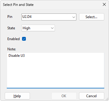
- Click on the
 Add button at the bottom of the control.
 - On the dialog that pops up, type U2.D4 in the Pin box.
- Set the state to High.
- Add a note that this is disabling U3.
- Click on the OK button.
- Repeat for the other constant pins listed above, with appropriate notes.
- Click the Next > button.
XJTAG v4.3.0