Checking the JTAG Chain
Now that the pins have been defined and the Test Reset Sequence has been set up, the user can confirm that the JTAG chain functions correctly. This is done by clicking the Check Chain button at the bottom of the screen, which initiates the following six steps:
- Runs the test reset sequence
- Counts the number of devices in the chain
- Uses AutoSkew to optimise timing for signal delays
- Reads ID codes
- Checks instruction register lengths
- Checks sample register lengths
The aim is to confirm it is possible to communicate reliably with all the JTAG devices, and that their register lengths and ID codes match the data in the relevant BSDL files.
- The JTAG chain can be checked from XJDeveloper and JTAG Chain Debugger. However, the difference is that XJDeveloper will know what devices it expects to see in the chain before the board is connected, whereas JTAG Chain Debugger needs to detect the chain to identify the devices; it then tries to match the identified parts to BSDL files in its library using the read ID codes. The consequence is that JTAG Chain Debugger will not know if it has been connected to the wrong PCBA.
Counting the Number of Devices in the Chain
Once the test reset sequence has run, the software will determine the number of devices in the chain. This allows the user to confirm all the JTAG parts are responding.
- To count the number of JTAG parts, all the devices are put into BYPASS mode by sending a long stream of 1s to the instruction registers and executing the resulting instruction (instruction registers are at least 2 bits wide, and a full set of 1s is always the command to insert the single-bit bypass register between TDI and TDO). The stream is sufficiently long that all devices in the chain will have received the necessary sequence before it is latched.
A pre-defined byte is then clocked into TDI and through the chain. TDO is monitored, and clocking continues until the transmitted byte has fully emerged. Because bypass registers are one bit wide, the number of clock pulses required to transfer the byte through the chain indicates how many devices it passed through.
The number of devices counted is displayed in the results pane; a typical example is shown below:
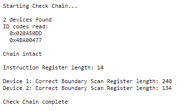
Figure 14: Typical Results When a Chain is Checked
- There can be valid reasons for reporting more ID codes than there are devices on the board: a multi-core IC, for instance, may show up as more than one device.
Timing Optimisation Using AutoSkew
Before the software attempts to read the devices' registers, it uses a feature called AutoSkew to optimise the timing of the data sampling to give best performance. This allows the system to compensate for the delays of any buffers in the chain, the effects of the cable, and the response time of the JTAG devices themselves.
- AutoSkew works by changing the state of TDI, applying a TCK transition, and monitoring how many fractions of a clock period it takes for TDO to alter. From then on, the software always applies this delay to ensure it consistently samples TDO at the optimal point for reliable readings.
Reading ID Codes
The ID registers are now read to confirm BSDL files with matching ID codes are available in the library (NB: not all devices have an ID code).
- The ID code (if supported) is always 32 bits long with an LSB of 1. If a device does not have an ID register, an attempt to read it will always return a 0 from the bypass register instead. When the data is clocked out, if the first bit seen is a 1, it is known that the subsequent 31 bits will be the remainder of an ID register. If a 0 is read, it is known that the part has no ID register and the following bit will therefore be the first from the next device. In this way, the serial data that exits the chain provides the ID codes of all devices and their relative positions, and identifies which ones have no ID register.
- The JTAG Chain Debugger performs ID code matching in a different way to XJDeveloper: in XJDeveloper, a BSDL file is assigned to each JTAG device as part of the project creation, and when the CHECKCHAIN function is run, the software confirms each device's ID Code matches that of its associated BSDL file and that they occur in the expected order. However, when a chain is checked from within the JTAG Chain Debugger, the software reads the ID codes from the devices and attempts to find a BSDL in its library with a matching ID.
If the reading of ID codes was successful and suitable BSDL files were located, the software reports that the chain is intact. If the JTAG Chain Debugger was unable to find BSDL files with matching ID codes, it will report that the boundary scan register could not be verified, in which case the user needs to load the appropriate BSDL file.
The device's manufacturer can be contacted to obtain the necessary file; links to common manufacturers' libraries are available on the XJTAG website.
Further advice on solving problems that occur due to ID code mismatches can be found in the debugging section of this guide.
Checking Lengths of Instruction Registers
The next step is to verify that the sum of all the instruction register lengths matches the sum of the values in the BSDL files. If they do not match or if a BSDL file with the correct ID code is not available, the test will stop running at that point.
- A pre-defined byte is clocked through the chain of instruction registers, and the number of clock pulses required to pass it right through the system gives the sum of their individual lengths. The software compares the total length it measured with the sum of the lengths stated in the BSDL files.
Checking Lengths of the Sample Registers
This check confirms that the length of each device's sample register matches the size stated in its BSDL file.
- The first device is put into SAMPLE mode and the others are placed in BYPASS. A pre-defined byte is then clocked through the chain, and the length of the sample register is determined by counting the number of clock pulses required for the byte to pass through the entire system (each device in BYPASS mode adds one additional bit to the total count because bypass registers are one bit long). This is then repeated for each device in the chain, and the register lengths are compared to the figures in their BSDL files.
Because determining the size of a device's sample register requires the other devices in the chain to be placed into BYPASS mode, the software needs to know the length of their instruction registers. If it has been unable to find BSDL files with ID codes that match the devices on the board, the user will be asked to provide the files. Alternatively, the user can manually input the length of the instruction register when prompted.
If a BSDL file is missing, go to the Device Configuration tab and, with the device highlighted as shown in Figure 15, browse to its location by clicking Browse...
If multiple BSDL files with the correct ID Code exist, the user is prompted to select the correct one from a dropdown menu of options.
If the user does not have a BSDL file, it is possible to manually input the instruction register's length by removing the tick from the Use BSDL File box (Figure 15) and then selecting the length from the options that are subsequently offered.
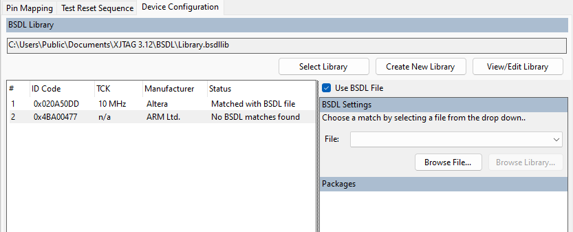
Figure 15: Dealing with Missing BSDL Files During a Check Chain Test
Use of Test Reset Sequences When Running the Chain
When the test is run to check the chain from the Pin Mapping screen, the Test Reset Sequence is run at various times as shown below:
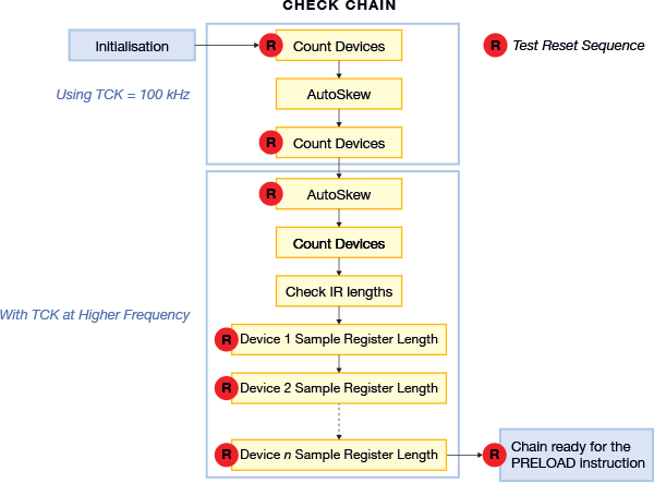
Figure 16: Test Reset Sequence: use when checking a chain from Pin Mapping screen
The sequence of events that occur when the chain is checked from the Run Tests screen is similar:
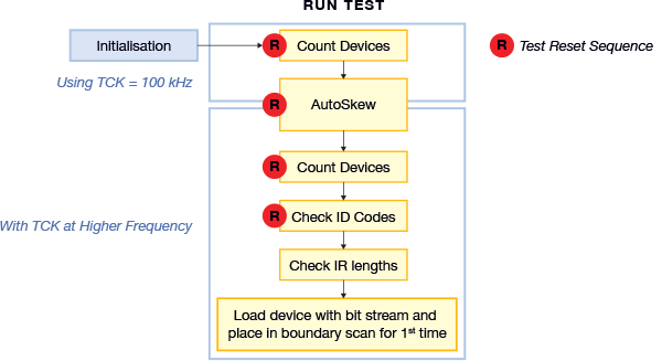
Figure 17: Test Reset Sequences: use at start of Run Test
XJTAG v4.3.0