Categorising Test Devices
Devices that will be tested or controlled using an XJEase function are described as Test Devices. They range from simple components such as LEDs and push buttons to ICs such as memories, ADCs, accelerometers, etc. When categorising a device as Test, a test device file must be assigned. This file can contain XJEase code as well as providing information about the device's pins.
There are two situations in which a device should be categorised as a test device:
- when you want to interact with it using an XJEase function. This is normally to test the device, but can additionally set it up (e.g. the file containing functions that test a Power Management IC might also be used to enable its outputs so that other circuit blocks are powered ready for testing).
- when you need to stop it interacting with other devices during a test (e.g. to keep a memory inactive so that it doesn't drive its data lines). This can be done by setting a Disable value in the test device file.
If there is insufficient access to the device to be able to control it, or there is no way to get feedback that it has correctly reacted to that input, it is unlikely the device can be tested. It is therefore important to check the level of access to the device before categorising it.
Categorising a Device as Test
The five steps to categorise a test device are therefore as follows:
- Confirm some sort of feedback can be obtained from it or that it will impact other tests if action isn't taken to prevent it.
- Check the level of access available to the relevant pins (and, if necessary, fix any problems that may be reducing access).
- Categorise it as a test device.
- Select the relevant test device file or create a new one.
- Set any configuration variables.
These steps are described in detail in the following sections.
Checking The Level Of Access
The level of access to a device can be determined by using Explorer. It is important to have already categorised anything that provides additional access such as logic devices, series resistors, FETs, etc.
To open Explorer, right-click on the device and select Show in Explorer from the context menu:
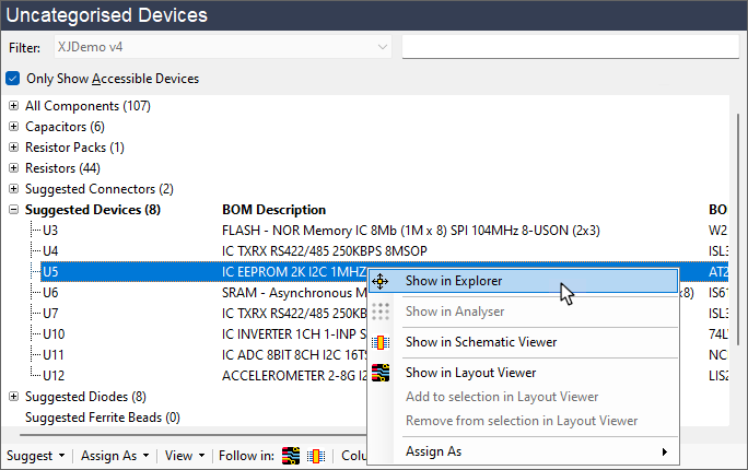
Figure 19: Opening Explorer to Check Level of JTAG Access
Explorer will then show the details of the selected device as illustrated by the example of Figure 20 below. The Access column shows the level of access to each pin. In this instance, it can be seen that there is JTAG read and write access to all the non-power pins. In addition, because we have control of the signals that make up an I2C bus, the bus can be used as a way to get feedback. The device can therefore be tested and should be assigned as Test.
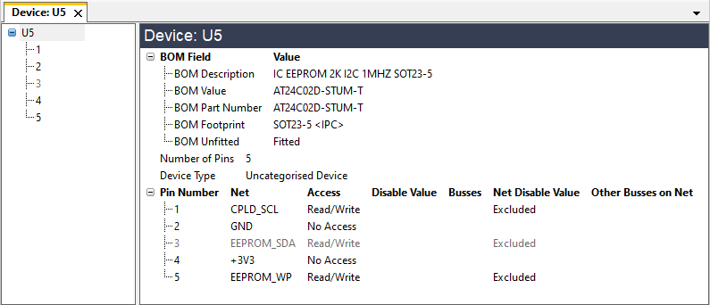
Figure 20: Using Explorer to Check Access to a Device
- The Net Disable Value and Disable Value columns show any access restrictions applied to the nets during a connection test. Although you may wish to confirm that these disable values are the expected default values for the nets, they will not affect your ability to test the device using XJEase because functions in the test device file can override them.
- Explorer shows a Net Disable Value of Excluded for the accessible pins in the example of Figure 20 because the device hasn't yet been categorised, and Connection Test will not drive nets connected to an uncategorised device.
The access for each pin is shown in the Access column. There are three types of access:
- Direct access from a JTAG device
- This could be either read-only, write-only, or both read and write. Figure 20 above illustrates how direct Read/Write access is shown. Direct access includes access that comes through passive linking devices such as low value series resistors.
- Access to a pin that passes through logic gates
- In these situations, XJDeveloper will automatically identify the possible signal routes, provided the logic has been correctly categorised. This type of access is shown in Explorer as Read (logic), Write (logic), or Read/Write (logic).
- Access to a pin via external hardware
- External hardware such as the XJLink2 or an ICT machine can be used to access pins in the unit under test instead of using a JTAG device. This type of access is described in Explorer as NJTE (Non-JTAG Test Equipment).
When there is more than one type of access, they will all be shown in Explorer as in this example:
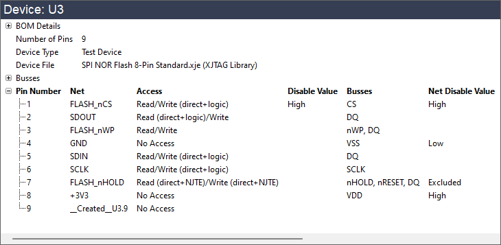
Figure 21: Example of Different Types of JTAG Access
If Explorer shows the expected level of access isn't being achieved, you can use Explorer to navigate through the different signal paths to see what is causing the problem. A net could be suffering reduced access because it's thought to be connected to power or because there's a device connected to it that hasn't yet been categorised. A net will show No Access if it connects to a power or ground rail, so if a signal net is shown as No Access, it might be because a pull-resistor has accidentally been categorised as a series resistor. If a net is marked as Excluded, that can indicate that a pin of an uncategorised device is on the net.
Having identified the cause in Explorer, you can then correct the problem before returning to categorise the test device.
- Full details of how to use Explorer can be found in the user guide chapter on Finding Information Using Explorer & Viewers. For guidance on how to use Explorer to find the source of the reduced access, and to see examples of typical causes, refer to the chapter on Using Explorer to Increase Test Coverage.
Once you know there is sufficient access to perform a test, categorise it as a test device by selecting it in the Categorise Devices screen and clicking the Test tile.
Selecting a Test Device File
Categorising a device as Test will open an Assign Device as Test dialog box similar to this:
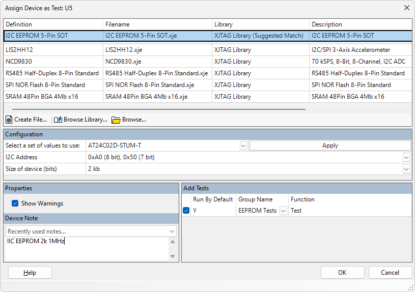
Figure 22: Assigning a Device as a Test Device
If the library has a file that matches the device's part number, it will be shown above the grey bar (1).
- If you used the Suggest method to categorise test devices, you will now only need to categorise ones with part numbers that don't match a library file. Therefore, nothing will be shown above the grey bar in that situation.
If a matching file hasn't been found (e.g. because the BOM doesn't have part numbers), the libraries can be searched manually by clicking Browse Library....
When a file is chosen in the library browser, the Details tab shows the pins that the functions will use. This allows you to select the correct file, even when the filename doesn't make the footprint obvious.

Figure 23: Checking the Pins for a Test Device File
In the above example, the file for this 8-pin SPI NOR flash assumes the Chip Select pin on the package is pin 4, the clock is on pin 2, etc.
- The XJEase library browser is a modal pop-up, meaning you cannot operate the main XJDeveloper window in the background while it is open. However, if you open Schematic Viewer and/or Explorer before starting to allocate devices as Test, those tools can be used to check pin numbers alongside the library browser.
- To view the XJEase code for a test device file, right-click the filename and select View from the context menu.
If a suitable file is not available, a new one will need to be created. See the user guide chapter on Creating Test Device Files for details of how to do this.
- To make the new Test device file readily available for use in other projects, it can be added to a user-defined library once it has been created.
- When there is access to a device's I2C bus, it is always possible to do a Check Present test to confirm it acknowledges its address. This simple test will verify that the I2C pins are not open circuit, that the device is powered, and that it is correctly fitted. If XJDeveloper detects that the device you are categorising has an I2C bus and there isn't a test device file in the library for its part number, XJDeveloper will offer to create this basic test for you automatically.
Setting Any Configuration Variables
Configuration variables allow one test device file to be used for similar devices. For example, an I2C device may have an address that is configured via its pins. In that case, the value that defines the address in the test device file could be a configuration setting, allowing it to have different values for each device that uses the file.
The middle section of the Assign Device as Test dialog box is where any configuration variables are set (Figure 24). If the file does not use configuration variables, this section will not be shown.
Figure 24: Setting Configuration Variables
If XJDeveloper found an exact match in the library, it will pre-fill the configuration values. If you need to provide the values yourself, it's normally easiest to set them at this point, although you can also fill them in later. Failing to fill them in will cause an error and stop the project running.
- Notes can be added to the Properties section. For example, they could be used to indicate when a file still needs XJEase code to be written – it's normal to categorise all Test devices at once, rather than stopping to write XJEase code for each one as you go along, so such a note can be a useful reminder.
- XJTAG also recommends notes are used to describe what the device is, whether the file is being used to test a device or only to ensure it doesn't interact with others during a test. Notes added here will be visible when categorising devices and are particularly useful when you or someone else reviews the project later.
Once any configuration variables have been set and explanatory notes added, click OK to complete the assignment.
Categorising JTAG Devices as Test
There are a few occasions when a JTAG IC should be categorised as both a test device and a JTAG device, although this is uncommon. It should only be categorised in this way when it is necessary to use the device without it being in boundary scan mode, such as when it needs to be preconfigured before it will fully enter that mode. Another scenario in which this would be required is when testing a JTAG-enabled Ethernet PHY using an external loopback. In that situation, it would need to be categorised as Test so that the necessary XJEase code can be run. However, when a JTAG IC is treated as a test device, it cannot control its own pins while it's being tested, and any relevant nets therefore need to be driven by another device. If nets need to be controlled but this cannot be done using another device, there is no benefit in categorising the device as Test.
- An IC should only be categorised as both a JTAG device and a Test device when it is necessary to associate it with some XJEase code. It is not required for the connection test.
To categorise a JTAG IC as a Test device, select it in the bottom-left JTAG Devices section and click Assign as Test:
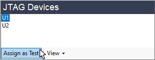
Figure 25: Assigning a JTAG Device as Test
When the device has been given a test device file, it will appear in the list of test devices as well as in this list of JTAG devices.
Creating a Test Device File to Hold a Pin's State
If you need a test device file solely to hold the state of one or more pins (e.g. to prevent a device interfering with other tests), it is likely you will need to create a new test device file. It does not need to contain any XJEase code, but just the bus definitions and the values at which the relevant pins need to be held (i.e. their Disable values).
For details of how to do this, refer to the guide on How to Create Your Own Test Device Files.
- Because defining a Disable value is a quick task and you will have most of the required information available during the categorisation, it is more efficient to create the test device file and set the Disable value at that stage rather than leaving it to later, provided the file doesn't require any XJEase code.
- It can be helpful to add a note to the test device file that explains the file was only created to set a Disable value and is therefore not expected to contain XJEase code. An explanation of why the device isn't also being tested can be a useful addition.
XJTAG v4.3.0