Add Board Dialog
The Add Board Dialog, shown below, allows you to add a board to your XJTAG project. The dialog prompts for the board's name, a description of the board and for the path to the netlist. Depending on the netlist format further parameters may also be required.
See Netlist formats below for more details on specifying a netlist.
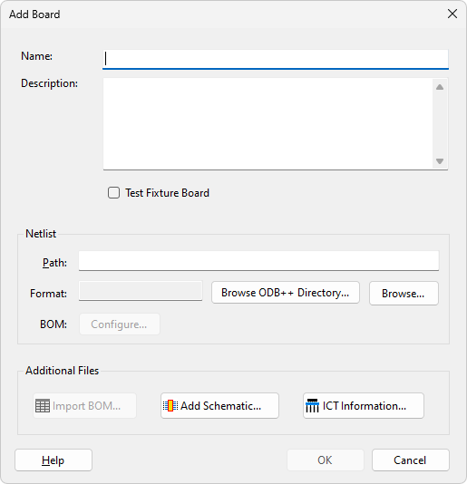
Checking the Test Fixture Board check box marks the board as a test fixture board. This implies that it is a board connected to a UUT board to extend test coverage and is not directly being tested. It is possible to reduce the fault information output by the connection test for boards marked as test fixture board by changing the "Reduce output for test fixture boards" setting in the Connection Test Settings.
Clicking the BOM Configure... button launches the Import BOM dialog, allowing BOM information contained in the netlist to be configured.
Clicking the  Import BOM... button launches the Import BOM dialog that allows you to add BOM information about your board on creation.
Clicking the  Add Schematic... button launches the Assign Schematic Files Dialog that allows you to assign any schematic PDF files to your board on creation.
For boards with PDFs assigned, the Schematic Viewer can be used to visualise elements on the boards schematic.
Clicking the  ICT Information... button launches the Edit ICT Information Dialog, which allows you to select the type of ICT machine to be associated with the board and import the information about the it.
Netlist Formats
The XJTAG system recognises many types of netlist, for example RINF, EDIF, PADSPCB and PROTEL. When a netlist file is specified the system will automatically determine the file type and load it. If this is not possible an error message will be displayed. If this happens, try to export a different format netlist from your design software. If the netlist contains suitable BOM information then XJDeveloper will attempt to identify any data for the built-in BOM fields and prompt you to automatically import data. Alternatively all available information can be viewed and configured by clicking Configure... button.
If your circuit design software is not capable of producing netlists in a format which XJTAG can import, please contact XJTAG. We can usually convert it and send it back to you, and it may allow us to support additional netlist types in future versions of XJTAG.
XJTAG also supports ODB++. This is a format originally developed by Valor and contains CAD, assembly and PCB fabrication data. Click Browse ODB++ Directory... in the Add Board dialog to select a directory containing ODB++ elements, or click Browse... to select an ODB++ file; the format will be automatically detected. For boards with an ODB++ netlist, the Layout Viewer can be used to visualise elements on the board.
Editing a netlist
If the netlist file is changed, XJDeveloper will attempt to re-apply all other settings for the board (e.g. power nets, component categorisation, constant pins etc) to the new board, so that minor fixes to a netlist cause minimum disruption to an existing project. If this is not possible a list of errors will be displayed.
NB: For minor tweaks to a netlist, edit the netlist path to point to the new file. For large changes (i.e. completely different board) it will be easier to remove the existing board and add a new one.
XJTAG v4.3.0