Checking DC Voltages
Using the Chain Debugger to Check DC Voltages Before First Use
Before using the JTAG chain for the first time, there are several checks that should be performed to ensure the cable is correctly made and seated, and that the lines are being held in the correct states to work. These preliminary checks are done by connecting the system and using the JTAG Chain Debugger.
- It is strongly recommended that these checks are not ignored: failures found during these initial tests can often be attributed to issues such as power rails not being powered when needed, incorrect connector wiring or wrong reset states.
Confirming DC Voltages
The first step of testing the JTAG cable is to use the JTAG Chain Debugger application (or the Pin Mapping screen in XJDeveloper) to measure the DC voltages on the lines: on the Pin Mapping tab, select the Safe pin mapping from the Load Preset dropdown menu. This will remove all pin allocations.
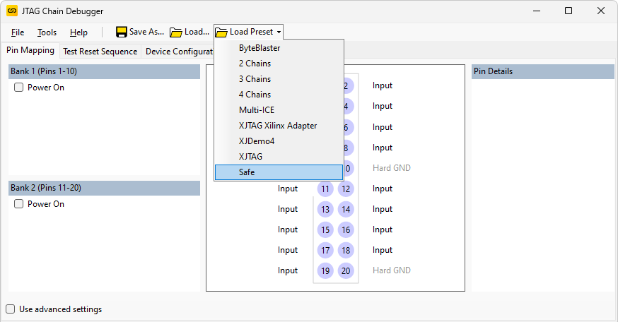
Figure 5: Setting a safe pin mapping
Now power-up the board under test.
- Customer boards should be powered from a bench power supply and not from the XJLink's power output, which has very low current capability. The Power On boxes are therefore left unticked.
- Rather than using a wall power adaptor, a bench PSU is recommended because its current limiting capabilities and display of output current are often a good indicator of the board's state.
For each pin in turn, click on the pin number, which will then cause the measured voltage to be displayed.
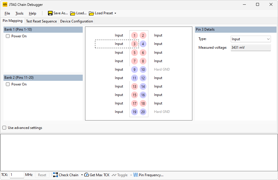
Figure 6: Measuring voltages
For each pin, check the voltages are as expected. This will then have checked the cable, the physical connection to the board, and the JTAG pull-ups and -downs.
- When using the Pin Mapping screen within XJDeveloper, the Live Mode needs to be set to On for continual voltage readings; within JTAG Chain Debugger, it is always live.
Debugging DC Voltages
If the reported voltages are not as expected, the Chain Debugger can be used in conjunction with an oscilloscope or multimeter to locate the error. To make this easier, it is possible to use the toggle button at the bottom of the screen to toggle the selected signal a few times a second.
- If using this feature to test a TDO connection, the user should first check the impact on the board under test (for example to confirm there is no buffer on the board's TDO output that would drive against the signal from the XJLink).
- Take care when using the Toggle Pin feature to ensure a fault has not imposed a conflicting voltage on the net under test.
To set a line toggling, first define the relevant pin as PIO in the Pin Details section and then select Toggle Pin at the bottom of the screen:
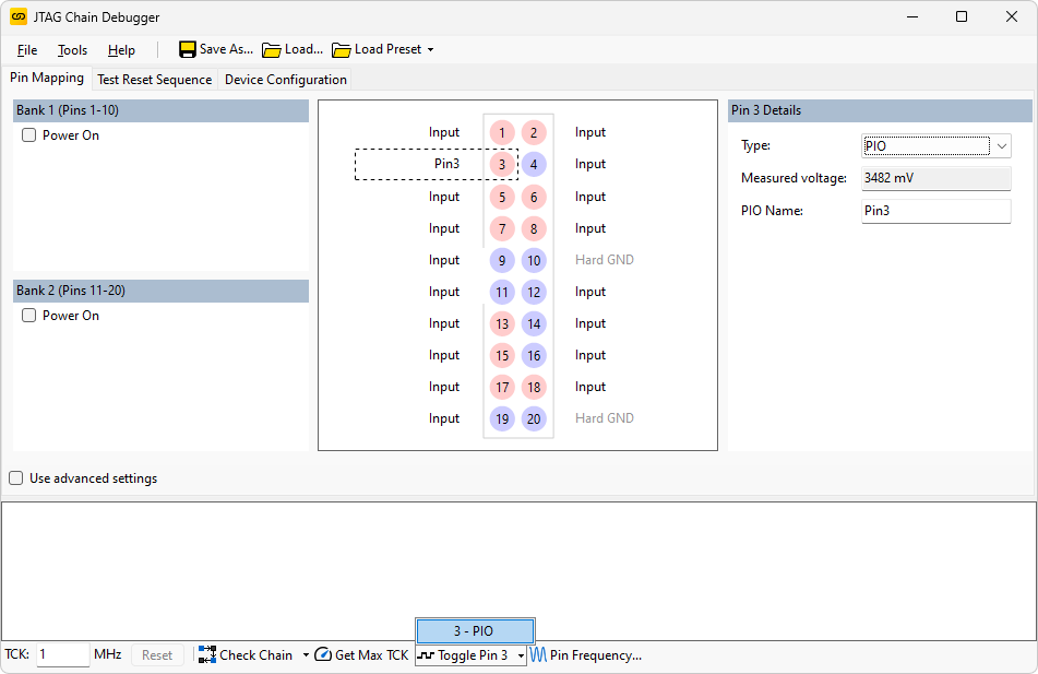
Figure 7: Toggling PIO pins
XJTAG v4.3.0