Using the Layout Viewer
The layout viewer can be opened from XJDeveloper by right-clicking on a device, pin, or net, and selecting the appropriate option from the context menu (provided the project contains layout information). This will open the viewer with the appropriate device, pin, or net highlighted. It can also be opened from Explorer (via the right-click context menu), and from hyperlinks in Connection Test's error reports and XJEase output text.
The layout viewer can automatically update the device / net / pin it is showing based on your selection in Explorer, the  Categorise Devices Screen, and the
  Power/Ground Nets Screen by ensuring the Follow Selection toggle button is enabled within the dialog or screen.
The layout viewer is also available in XJInvestigator and XJRunner if the currently open project was exported from XJDeveloper with layout data included.
The layers that are necessary to view the relevant net(s) will be switched on automatically.
- The layout viewer can also be opened at any time using any of the following methods (provided the project contains layout information):
- use the Ctrl + J keyboard hot key
- select View > Layout Viewer from XJDeveloper's menu bar
- select Tools > Layout Viewer > Select from XJDeveloper's menu bar and choose Device..., Pin..., or Net...
- click the
 button on XJDeveloper's toolbar
This section covers the following topics:
- View boards from the bottom side instead of from the top
- Find a net or device by its name
- Viewing multiple nets simultaneously on the layout
- Capture a screenshot
- Navigating around the board
Viewing Boards from the Bottom Side
By default, the board is viewed from the top side, and components on the bottom of the board are therefore viewed through the PCB. To view the board, instead, from the underside, click the  Toggle Bottom View button in the toolbar or select View > Bottom View from Layout Viewer's menus.
Finding a Net or Device by Name
To search for a net, device, or pin by its name, type into the Find: box at the top of the screen. The syntax for a pin when using this search box is <device name>.<pin>: for example, U7.2 or U8.A3.
Items can also be found using the Selectors pane (see Figure 24 below): select either the Nets or Devices tab and find the required item(s) in the displayed list. To filter the list, type part if its name into the Filter: box. The selected item(s) can now either replace the existing highlighted items or be added to what is already shown:
- To replace what is currently highlighted: double-click on the item in the list.
- To add the selected item(s) to the existing highlights: right-click on the item(s) in the list and select Add to Selection in Layout Viewer.
- By default, double-clicking on the item will replace the existing highlighted items with the new selection. This default can temporarily be changed by clicking the Multiple Selection button in Layout Viewer's toolbar:
Multiple Selection button - The button will be outlined in blue when the default is add-to-selection.
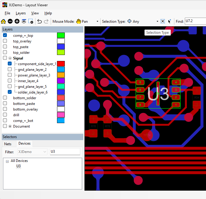
Figure 24: Using the Selector to Find a Particular Net, Device, or Pin
To clear the current selection, click the ![]() Clear Selection button in Layout Viewer's toolbar or right-click on the layout and choose Clear Selection from the context menu.
Clear Selection button in Layout Viewer's toolbar or right-click on the layout and choose Clear Selection from the context menu.
Viewing Multiple Nets Simultaneously
When debugging a board and looking for points where two nets could be shorted, it can be useful to highlight both nets simultaneously on the layout. When the viewer is launched from a hyperlink in a test output message that identifies shorted nets, this will be performed automatically. To show multiple nets manually:
- Display the first net in the layout viewer (for example by searching in the Selectors pane).
- Right-click on the name of the other net (e.g. in the Selectors pane or in the test results) and choose Add to selection in Layout Viewer.
- Both nets will now be displayed with the scaling automatically adjusted.
Capturing Screenshots
An image of the main panel can be captured in a range of formats by selecting File > Export Image from the menu bar.
Navigating Around the Layout
There are various mouse modes, which can be selected from the toolbar's Mouse Mode: dropdown menu:
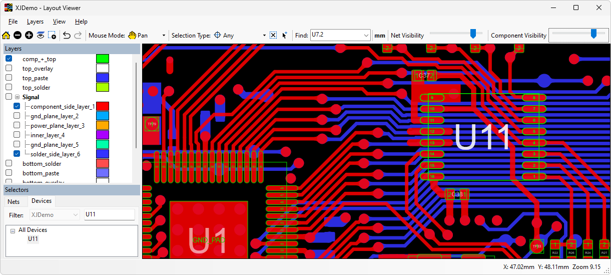
Figure 25: Navigating Around Layout Viewer
| Desired Action | Instructions | Comments |
|---|---|---|
| Pan across the layout. | Select Pan from the Mouse Mode: dropdown menu. Hold down the left mouse button and drag the display. | |
| Zoom to a selection. | Select Zoom from the Mouse Mode: dropdown menu and draw a box round the desired area by holding down the left mouse button. | |
| Highlight the complete net by clicking on part of it. | Choose Select from the Mouse Mode: dropdown menu and left-click on the net to be displayed. If necessary, turn on additional layers. | To display multiple nets, toggle the Multiple Selection option from the right-click menu.
To un-highlight the nets, right-click and select Clear Selection. |
| View net name and which pins are connected to it | Choose Tracking from the Mouse Mode: dropdown menu and hover over a net, device, or pin. |
You can zoom in all modes by holding down the Ctrl key and using either the scroll wheel or the + and - keys.
The transparency of unselected nets and component outlines on enabled layers can be adjusted with the sliders at the top of the screen as shown in Figure 25 above.
- Mouse modes can also be selected by right-clicking anywhere on the layout and selecting Mouse Modes from the context menu.
Taking Measurements on the Layout
Measurements between items on the layout can be made by switching the mouse mode to Measure using the Mouse Mode: menu as shown in Figure 26.
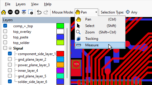
Figure 26: Making Measurements on the Layout
Three measurement options are available, which can be selected using radio buttons in the Measure box that will open:
- Point measures between any two points on the layout.
- Component or pin centre measures between the centre points of two items on enabled layers.
- Net or pin pad measures the minimum distance on enabled layers between the pads of two pins, the minimum distance between the centrelines of two tracks, or the distance from the edge of a pad to the centreline of a track.
To make a measurement, click once to register the first point or object, and then click on the second point or object. In Component or pin centre mode, the measurement point will automatically jump to the centre of the item.
When a measurement is made, the pan and zoom will automatically be adjusted to show the point at which the measurement was taken, marked by a white line.
Because objects may have different geometries on the different layers, the measurements for items that span multiple layers are shown for each layer.
- Because nets do not have centres, clicking on a net in Component or pin centre mode will jump the cursor to the closest object.
To pan while measuring, hold down the Ctrl key and drag the mouse. To zoom while measuring, use the  and
and  buttons on the toolbar, or use the mouse scroll wheel.
XJTAG v4.3.0