Defining JTAG Chains
The JTAG signal path, starting at a circuit's TDI input, passing through the interconnected JTAG devices, and ending at the circuit's TDO output is known as a JTAG chain. It can contain one or more JTAG devices and is the way in which the test data is moved through the circuit being tested. A typical chain is shown in Figure 1:
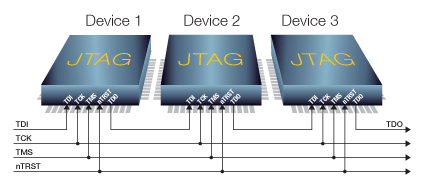
Figure 1: A 3-device JTAG Chain
The interconnections may be direct as shown above, or might pass through links, buffers, or low value series resistors. A circuit can have multiple independent JTAG chains, and chains may span several PCBs in a multi-board system.
As part of setting up a project, XJDeveloper needs information about how the devices in the JTAG chain(s) are connected. For each chain in the circuit, the following data needs to be defined:
- The points in the circuit where each JTAG chain starts (TDI) and ends (TDO). These might be pins on a connector or test points.
- Details of the JTAG devices in the chains, provided by their BSDL files.
- Details of any other devices in the signal path such as series resistors or buffers.
This information is entered in XJDeveloper's JTAG Chain screen, which can be found in the list of screens under the Setup header:
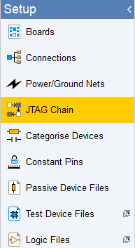
Figure 2: Accessing XJDeveloper's JTAG Chain Screen
The chain(s) can be defined manually or semi-automatically. It is normally easiest to allow XJDeveloper to attempt to find the chain(s), and then to manually complete the definition(s) if required. This chapter describes both options.
- The XJLink2 JTAG controller supports up to four independent chains. They can run separately or be used together during a test to give better test coverage.
XJTAG v4.3.0