Device Categories
Accessible devices should be assigned to one of the six categories described below. Although a circuit can be tested with accessible devices left uncategorised, categorising them will give the best test coverage.
An overview of how to use the different categories is shown in the following flowchart:
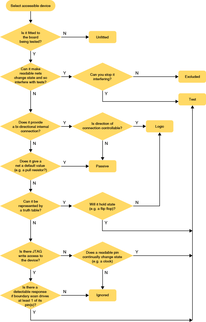
Figure 3: The Different Device Categories
The Test Category
Categorising a device as a test device associates it with an XJEase test script file. A device is categorised in this way for one or both of the following reasons:
- To allow it to be tested
- In this situation, the associated file will include test functions describing how to interact with the device to perform testing. This applies from simple devices like an LED (where the test will be to illuminate it) to complex ones like a DDR memory (where the test writes and reads memory locations).
- To ensure it won't interfere with another test
- In this situation, the associated file is used to apply a Disable value to one or more pins to keep them at a fixed value during the connection test. For example, it might be necessary to keep a regulator switched on by holding its Enable pin in the active state.
A single test device file can perform both jobs. For example, the file containing XJEase code to check a memory can also define a Disable value to de-assert the memory's Chip Select during the connection test to ensure it won't drive nets at that time.
For information on how to create a test device file and write XJEase test functions, please refer to the relevant user guide chapter.
- A Disable value is applied when the JTAG chain is initialised. It will be maintained throughout the connection test and will persist afterwards unless a test device file changes its value.
- Disable values have the same effect as setting a Constant pin , but which approach is best to use will depend on the circuit being tested. For example, in a circuit that uses several of the same device in the same way each time, the best approach is to define a Disable value in the test device file because the value then only needs to be set once. By contrast, using Constant pins in that example would require the same value to be defined multiple times, once for each device. However, in a circuit where a device is used several times but only one of those instances requires a pin's state to be fixed, a Constant pin is the best approach
- When a device has several pins that need to be held, it may be appropriate to use a mix of Disable values and Constant pins. For example, if the device is used in several places, the pins that always require the same value can be set using Disable values, and the device's pins that need different values in different circuit positions could be set using Constant pins.
- If a Disable value and a Constant pin try to apply different values to the same net, the Constant pin will take priority (the Help system defines the full list of priorities). If two test device files try to set different values on the same net, the system will decide which one to apply. In both instances, a warning will appear in the Warnings tab that will show which value has been set.
- Because a Constant pin takes precedence over a Disable value, a Constant pin can be used to resolve the problem if two test device files try to set different disable values on the same net. This solution avoids the need to edit the test device files.
When a Disable value or Constant pin is set, Connection Test will apply a default value to the appropriate net and will not change it during the test. This will reduce the coverage achieved by Connection Test, and XJEase functions will therefore be needed to check those nets in a different way.
- XJEase functions can be run from both test device files and circuit code files. A test device file is used to test an individual device using elements of its own functionality. If several devices need to be used together as part of the same test, a circuit code file should be used to control the interactions between those devices. See the user guide chapter on Creating Test Device Files for more details.
The Passive Category
A device is categorised as Passive if it connects nets together in some way or gives a net a default state (e.g. a pull-resistor). Categorising like this will assign a Passive Device Description file to the device to tell XJDeveloper how it behaves (e.g. to differentiate a pull-resistor from a series resistor or a termination resistor). These model files are described later in the section on Types of Passive Device.
Most of the devices categorised in this way are likely to be series resistors or pull resistors, but this category will also include devices such as ferrite beads and inductors that are used to link power nets together. If your circuit has a DDR interface that uses bias termination or differential termination resistors, they will placed in the Passive category (but with different model files to each other); if IEEE 1149.6 testing is being performed, the relevant coupling capacitors will also be categorised as Passive.
The Logic Category
The Logic category is used to describe devices that join two nets together but don't make the straightforward bidirectional connection that a series resistor creates. Categorising a device in this way associates it with a Logic Device Description that describes its functionality. A device can be categorised as Logic when it can be defined by a truth table and doesn't hold state. For example, a NAND gate or a buffer can be categorised as Logic, whereas a bistable flip-flop cannot, and would need to be set as a Test device instead.
The advantage of categorising a device as Logic is that the system will then control it automatically and know how to deal with the unidirectional nature of the signals. For example, Connection Test will automatically test a logic device if there is JTAG access to its inputs and outputs; the test will also know not to drive against an output. Outside of the connection test, categorising logic can greatly simplify the creation of XJEase tests because XJDeveloper can automatically work out how to use the logic to gain access to pins on other devices, and will take any signal inversions into consideration. It can also lead to increased test coverage because XJDeveloper can use the logic inputs to control other nets in the circuit, thereby extending test access.
However, it should be noted that there are some circuit configurations where it may be appropriate to categorise a logic device differently, for example as a Passive. This can be relevant if performance is important and the logic is particularly complex (e.g. a lot of cascaded logic) because categorising it as something other than Logic will result in a faster test – when interacting with logic devices, XJDeveloper needs to calculate what input values will be needed to generate each required output. Reducing the need for those calculations by categorising some of the logic as Passive can give a noticeable reduction in test time when the circuit contains complicated logic.
For examples of when this is appropriate, refer to the later section on When to Categorise Logic as Passive.
- If you have logic in your JTAG chain that allows JTAG devices to be switched in and out, you will need to set up dynamic chains.
The Ignored Category
A board might have devices fitted that can't be tested with XJTAG because there is insufficient access or they cannot provide detectable feedback to an applied stimulus. Provided such devices will not interfere with any of the tests, they should be categorised as Ignored. Examples of such devices include ESD protection diodes, RF-filtering capacitors, and connectors that have nothing connected to them.
Categorising devices as Ignored tells XJDeveloper it is safe to drive the nets connected to them, and Connection Test will therefore be allowed to check those nets for shorts and stuck-at faults.
The Excluded Category
A board might have a device fitted that can't be controlled but which will interfere with tests by trying to drive nets. This could apply to devices such as small non-JTAG microcontrollers that can't be disabled and so will be freely running their firmware, or to circuitry which is permanently enabled such as input transceivers, as shown below:
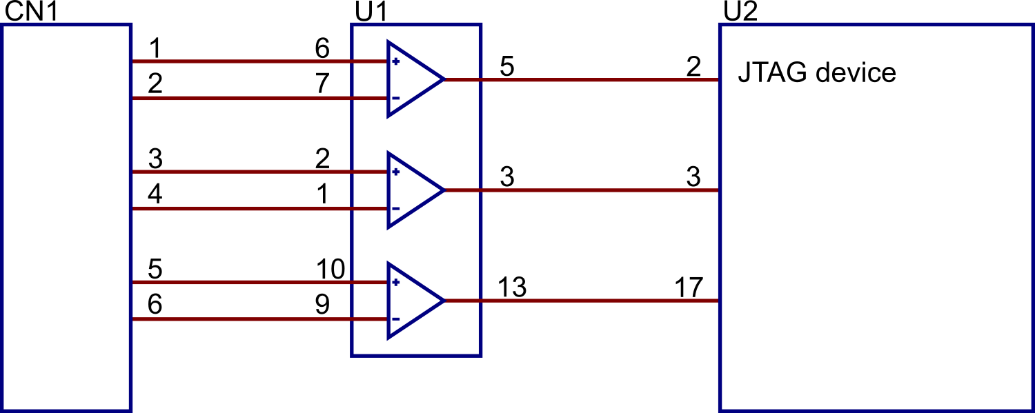
Figure 4: The Different Device Categories
In this example, the transceivers in U1 cannot be disabled and so must be excluded from testing as allowing U2 to set the pins could cause issues or test failures.
By categorising a device as Excluded, you are telling Connection Test that it must not drive any nets connected to the device. Its pins will be marked as untested in test coverage reports and the device will negatively impact the test statistics. It is best to try to avoid this category due to the impact on the connection test – most projects don't need to use the category.
The Unfitted Category
Components in the netlist that aren't placed during assembly should be categorised as Unfitted. This category is used for optional-fit devices that were added to the schematic to allow for design options, but also includes PCB features that appear in the netlist, such as fiducial marks, mounting holes, and test points.
XJDeveloper will suggest which devices should be placed in this category based on data provided when the board was imported. For more information, see the user guide chapter on Entering Board Information.
Devices placed in this category will be removed from the test coverage analysis, and their pins will not be included in the count of solder connections used for coverage calculations.
- It is recommended to temporarily remove the tick from the Only Show Accessible Devices box when assigning devices to the Unfitted category. This will help you to remove all unfitted devices from the test coverage calculation, whether they're accessible or not, giving the most accurate test coverage statistics.
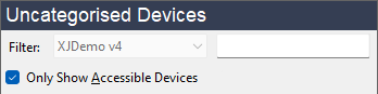
- It is important to replace the tick once categorisation of unfitted devices is complete so that only accessible devices are shown when you perform the other categorisations.
XJTAG v4.2.5