Overview
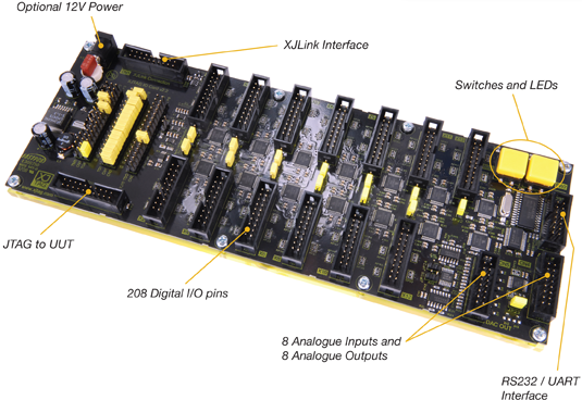
The XJIO board provides both digital and analogue input and output signals. By linking the JTAG chains of your Unit Under Test (UUT) and the XJIO board you create a single 'super chain'; when the I/O connectors on the XJIO board are linked to the UUT you will increase the proportion of nets on the UUT that can be fully tested with XJTAG.
IO Connections
Digital
There are 208 digital I/O pins organised as 13 banks. Each bank of 16 I/O pins is connected to a 20-way 0.1" (2.54 mm) connector. Three of the remaining pins are used for ground while the last pin can be used to provide an alternative power reference relevant to that connector. It is very important to ensure there is a good ground connection between the XJIO board and the UUT (this can be done by connecting as many of the grounds on the XJIO board as possible to ground signals on the UUT).
Analogue
There are 8 analogue inputs and 8 analogue outputs. The on-board ADC and DAC are controlled via serial communication with one of the JTAG devices. Typical uses for the analogue signals include checking power rails are within limits and stimulating analogue inputs to improve test coverage of the target board.
RS232
There are two RS232 devices on the XJIO Board. There is a RS232 transceiver to enable simple connectivity testing at RS232 signal levels and also a UART device to enable full RS232 communication testing.
Expansion
If you require more than 208 digital I/O pins, multiple XJIO boards can be daisy chained together via the external JTAG connector until you reach the required density.
Interaction
The switches and LEDs allow users to interact with their test system using the XJIO board rather than a computer keyboard and monitor.
XJTAG v4.3.0