Categorising Resistors
Categorising Resistors
Now that unfitted devices have been categorised, the tick in the checkbox at the top of the Uncategorised Devices list should be kept present because, from now on, it is only necessary to categorise accessible devices.
The next step is to assign the series resistors. XJDeveloper will suggest resistors for this category if they're not connected to power or ground and their value is below 100 kΩ (when value data is available in the BOM).
Categorisation is often quicker if the devices are first sorted by value, because resistors used in the same way in a circuit normally have the same value. Sorting is done by clicking the heading for the BOM Value column as shown in Figure 9 (this column will only be present if suitable BOM information has been provided).
- Resistor categorisation is simplified by having resistor values available. It is therefore recommended that BOM data is imported. If XJDeveloper does not have this information, more manual checking will be required.
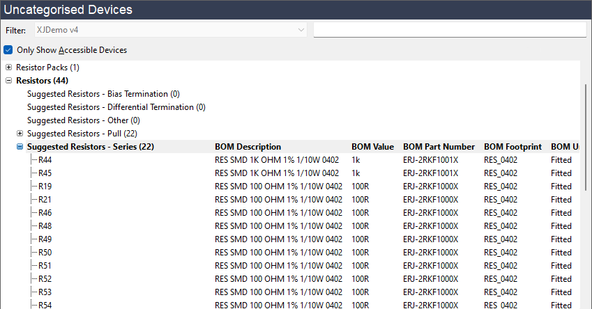
Figure 9: Sorting Resistors by Value
To confirm resistors are being used in the way that XJDeveloper has proposed (series, pull, etc.), right-click on the resistor and select Show in Schematic Viewer from the context menu.
- It is rarely necessary to check every resistor before accepting the proposed categorisations. The best approach is to check one resistor from each group of sequential reference designators. For example, in a circuit with ten 100 Ω resistors, R1–R5, R7, and R20–R23, it is probably adequate to check, for instance, just R1, R7 and R20.
Categorising a device as a resistor can be done as shown in Figure 10 below by selecting the device(s) and clicking the Passive tile. This will open the Assign Device as Passive dialog box, in which a Passive Device Description (*.pdd) file must be selected. This file tells XJDeveloper about the connectivity provided by the device, and is the way it differentiates between series resistors, pull resistors, and the types of termination resistors (for details of the different resistor types, refer to the section on Passive Device Description Files).
Alternatively, if the required Passive Device Description file has recently been used, the categorisation can be completed in a single step by selecting the device(s) and then clicking the required file in the Existing Files section:
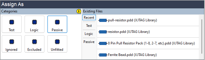
Figure 10: Categorising Resistors
When not using the Recent list, device categorisation will be done in the Assign Device as Passive dialog as shown in Figure 11 below. XJDeveloper's suggested file is shown above the grey bar, and files previously used in the project are shown below it.
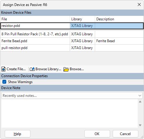
Figure 11: Using the Assign Device as Passive Dialog to Select a PDD File
To use an alternative file, use either Browse Library... to choose a file from a library or Browse... to locate a file stored elsewhere.
If a suitable file does not exist, a new one can be created by clicking the Create File... button. The process for creating a new file is described below in the section on Creating a New Passive Description File.
It is recommended that the Show Warnings checkbox is left ticked at this stage. It can be changed later if required but it's useful to keep warnings for Passive devices active during project development because they will warn of any connectivity issues.
To complete the categorisation, select the required model file and click OK.
Once all the series resistors have been categorised, continue with the pull resistors. XJDeveloper will propose resistors between 1 kΩ and 100 kΩ as pull resistors if one pin is connected to ground or a power rail. Again, it can be useful to sort resistors by value before categorising them (as described above) because resistors performing similar functions in a design tend to be given identical values, which makes it easier to identify any proposals that need further investigation before being accepted.
- Inadvertently categorising a pull resistor as a series device will cause nets to lose write access because XJTAG will not drive a net that is linked to power or ground.
Resistors that are not obviously Pull or Connect
Once all the series resistors and pull resistors have been categorised, any devices in the Suggested Resistors - Other section should be addressed. This group includes resistors that do not fit in one of the other categories, such as resistors that are not connected to power or ground but have values that fall outside the range for a series device (i.e. greater than 100 kΩ). It also includes resistors with potentially conflicting functions – for example, a potential divider would appear to have a pull-up and a pull-down resistor on the same net.
- To learn how to categorise resistors in a potential divider, refer to the section below.
Resistors placed in this section will be commented to explain why XJDeveloper has placed them there, as illustrated by this example:
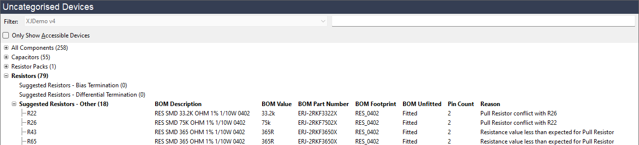
Figure 12: Reasons are Shown for Resistors in the Other Category
Categorising High Value Series Resistors
If a resistor is categorised as a series resistor, the system assumes that stuck-at faults on one pin will be detectable on its other pin. However, that won't be true if the resistor's value and the JTAG device's drive strength are both sufficiently high that the output pin can be driven to the correct logic level despite the short to power or ground on the resistor's far pin.
If the resistor goes to a device that cannot be tested anyway (such as a connector), nothing will be gained by categorising it as a series passive and it may therefore be simplest to categorise the resistor as Ignored. Categorising it in this way doesn't stop Connection Test detecting a short to a non-power pin at the far end of the resistor, so test coverage is not being lost in this instance. The advantage is that it removes the need to categorise devices beyond that resistor because they will no longer be accessible, saving time in project creation.
Note that when categorising these resistors as Ignored, the test coverage statistics will report the far pins as untested, even though some limited testing is occurring. The reported coverage will therefore be lower than is actually being achieved. In contrast, if they are categorised as series Passive, the test coverage statistics will report better coverage than is being achieved because it will be assumed stuck-at faults on nets connected to the far pins are also detectable.
Therefore, when categorising series resistors with values that are high enough for the JTAG device to drive against a stuck-at fault, XJTAG recommends that you consider what test coverage you will be able to achieve on the non-driven pin. If categorising the resistor as anything other than Ignored cannot give better coverage than detection of shorts to another pin, it is simplest to categorise the resistor as Ignored because those shorts will be detected anyway.
Categorising Resistor Packs
When categorising resistor packs, it is essential to consider the pin numbering and to select the matching Passive Device Description file. XJDeveloper will analyse the circuit and try to propose the most appropriate file, but you should check the pin-out used in the file against your circuit. To view it on the schematic, right-click on the device and select Show in Schematic Viewer from the context menu. If the schematic does not include pin numbers, you can use Explorer to examine the connections instead by right-clicking and selecting Show in Explorer.
- To see how to check pin allocations in Explorer, refer to Discovering How a Device's Pins are Connected in the Explorer user guide.
If all the resistors in the pack are used in the same way (e.g. all used as series resistors), XJDeveloper will place the pack in the relevant group (e.g. Suggested Resistor Packs – Series) and will subsequently propose a suitable resistor pack file from the library. However, if the resistors in the pack are used in a mix of ways, the pack will be placed in the Suggested Resistor Packs – Other group, and a customised Passive Device Description will be required. See the section on Creating a New Passive Description File for details of how to create a suitable file.
Potential Dividers and Pull Resistors
When resistors form a potential divider, how to categorise them depends on the circuit. If the resistors can be accessed with boundary scan, they should be categorised as either Passive devices using the Pull Connection Type, or Ignored devices, depending on the divider's output voltage. Four examples are shown below:
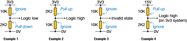
Figure 13: Categorising Resistors in Potential Dividers
In the first example, the divider's output voltage is a valid logic low. The 2K2 resistor should therefore be categorised using the Pull Connection Type and the 10K as an Ignored device. In the second example, the output voltage is a valid logic high and so, this time, it's the upper resistor that is categorised as Pull and the lower one is set to Ignored. In example 3, neither resistor pulls the output to a valid logic state, so the potential divider's resistors cannot be tested: both need to be set as Ignored devices.
Example 4 shows a similar configuration to the first one, except that the resistors divide down from a higher voltage. The output voltage now gives a logic high for a 3V3 system and so, if the JTAG device reading it is operating at 3V3, the configuration is similar to a pull-up: this time, the 10K should be assigned as the Pull and the 2K2 as an Ignored device.
- If the resistors cannot be accessed, they do not need to be categorised.
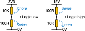
- If the pull resistor in the potential divider has a value that is too low to be driven against (and is connected to a pin with output capability), it should instead be categorised as a series resistor using the Connect Connection Type to prevent the net being driven; the other resistor should be categorised as Ignored:
- Remember, also, possible issues with pull resistors if their values are too large, as described in the description of the Pull resistor type above.
Termination Resistors
There are two types of termination resistor that XJDeveloper needs to know about, and the difference between them is illustrated below:
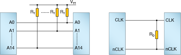
Figure 14: Different Types of Termination Resistors
Bias Termination Resistors: in the first example, each address line is terminated using a resistor that connects to a fixed voltage, VTT (frequently mid-rail). This arrangement is often used around DDR memories.
The connection test will often drive many of the device's pins to the same level simultaneously and then read undriven pins to ensure their values haven't changed. However, these simultaneous transitions can cause VTT to shift slightly and, because it is a mid-rail supply, this small variation can cause the read input to change logic state. To avoid this being incorrectly interpreted as a short circuit, the resistors (and VTT) must be given special categorisations; the resistors cannot be defined as Ignored devices.
The resistors cannot be treated as having the Connect Connection Type because that would extend the VTT power rail down to the device's pin, and XJTAG would therefore never drive the net. Nor can they be considered as having the Pull Connection Type because VTT is at mid-rail and therefore cannot reliably pull the nets to a logic high or low. Instead, these resistors must be given the Bias Term Connection Type, which is done by assigning them the Passive Device Description file, Bias Term.pdd. The software will then perform specific tests that check the relevant nets are resistively terminated and not shorted together.
Differential Termination Resistors: in the second example, differential signals are being used with a differential termination resistor, RD, placed directly across the two differential nets. This form of termination is common for many types of high-speed differential signal (for example, the clock input to DDR memories).
These resistors typically have values around 100 Ω, which is sufficiently low that if one of the nets is driven and the other isn't, the same value will be read on both nets. However, this resistor cannot be given the Connect Connection Type because this circuit configuration allows the two pins of the resistor to be driven to opposite values, and the nets will therefore not always read the same value.
The resistor therefore needs to be given the Diff. Term Connection Type. This tells the software that it is acceptable to drive the nets to opposite values and that, when it isn't driving them, the nets will behave as if shorted together (because of the resistor's low value). Allocating this Connection Type is done by assigning the Diff Term Resistor.pdd file.
There may be occasions when the differential resistance is made up from two resistors in series as shown in Figure 15 below. In that case, one resistor should be assigned as a differential termination resistor and the other as a series resistor.
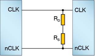
Figure 15: Two Series Resistors for Differential Termination
Centre-Referenced Terminations are those where the differential resistance comprises two resistors in series, with their mid-point AC coupled to a fixed voltage or ground. Figure 16 below shows a typical example.
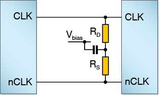
Figure 16: Differential Resistors with Centre-Referenced Terminations
As far as DC signals are concerned, this circuit is similar to Figure 15, and we therefore recommend you use a Diff. Term Connection Type for one resistor and Connect (i.e. a series resistor) for the other. However, the way this circuit responds during a boundary scan test is affected by its time constant and, in some situations, using a differential termination resistor and a series resistor may generate an error. If Error on terminated nets is reported with the information that the DIFF_TERM-Terminated nets should appear shorted at DC..., you will need to categorise both resistors as bias termination resistors and the net at the mid-point as a Termination Reference voltage.
XJTAG v4.3.0