Running the Connection Test
It is possible to start using XJDeveloper to test your circuit almost as soon as the description of the JTAG chain is complete. At this stage, the Connection Test can be used to test any net that only contains pins that are on the devices in the JTAG chain.
There are two methods of running tests:
- Using the
 Run Tests screen in XJDeveloper.
 - Using the XJRunner or XJInvestigator applications – when you have a working set of tests in XJDeveloper, you can export them to an XJPack file to allow XJRunner or XJInvestigator to run them.
In this tutorial we will use XJDeveloper to run the tests.
- Click
 XJRunner Setup under Run and Deploy.
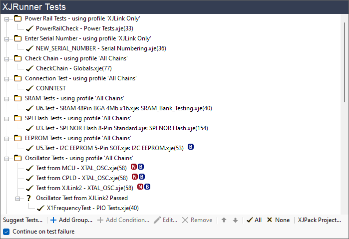
XJDeveloper has added two tests to the project automatically. These are displayed under XJRunner Tests. The first test is CheckChain (from the Globals.xje file). This checks the JTAG chain is working and that the ID codes of the devices in the chain match those that are expected.
The second test is CONNTEST. This is XJTAG's automated interconnectivity test. The ticks next to the tests indicate that they are set to run by default.
The list of XJRunner Tests can contain any functions in Circuit Code Files or Test Device Files which are defined as Global and which have a single INT output parameter that lets XJRunner know if the test has passed or failed.
Most XJTAG library device files contain a function called Test that matches this requirement and so can be included in the list.
Setting the Pin Mapping
XJDeveloper now has a minimal project representing the XJDemo board, and a list of tests to run. The final step needed before you can run those tests is to tell XJDeveloper how to configure the XJLink to communicate with the circuit under test. There is no industry standard for a JTAG header pin-out, and so the pin mapping of the XJLink is configurable.
The JTAG connector on the XJDemo board, P1, is designed to demonstrate various capabilities of the XJTAG tools. To allow these to be configured easily, you can select the required pin mapping for the XJDemo board from the list of built-in pin mappings.
First, however, you need to make sure you have the correct XJLink type selected.
- Click
 Pin Mapping under Run and Deploy.
If you are using an XJLink2 or PXI-XJLink2 for this tutorial:
- Check that the only entry in the Supported XJLink Types panel is called XJLink2.
If you are using an XJLink-PF series controller:
- Click Add XJLink Type at the bottom of the Supported XJLink Types panel.
- Select the type of XJLink that you are using in the dropdown to add a pin mapping for that XJLink.
- Now select XJLink2 in the Supported XJLink Types panel and click Remove XJLink Type at the bottom of the panel.
The only type of XJLink listed in the Supported XJLink Types box should now match the type of XJLink you are using. You have now selected the correct type of XJLink, but not yet selected the pin mapping (defined the functionality of each pin on the XJLink).
- From the Pin Mapping menu at the top of the XJDeveloper window, choose Load Pin Mapping Preset and then click XJDemo4 from the dropdown list.
- Click
 Save on the main XJDeveloper toolbar.
Check the Errors pane: the error we saw earlier should have disappeared because the pin mapping has now been set.
N.B. The preset XJDemo4 pin mapping for XJLink2 uses the XJLink2's capability to supply power to a circuit. This is not recommended for test systems due to the very limited power that can be supplied. The functionality is not present on XJLink-PF series controllers.
For some circuits, at this stage of the process it may be necessary to define a custom Test Reset sequence. For further information, read the XJTAG User Guide section on Test Reset sequences or see the help for XJDeveloper's Pin Mapping screen.
Connecting the Board
The XJLink is connected to the XJDemo board at connector P1, using the supplied cable. If you are using an XJLink2 or PXI-XJLink2, no extra power is required because the board will be powered by the XJLink2. If you are using an XJLink-PFxx controller the USB connection to the demo board adapter will provide power to the board, and the XJLink-PFxx controller will switch that power on and off as required during tests.
Running the Tests
- To run the tests, click Run Tests under Run and Deploy.
- Then click
 Run.
Run.
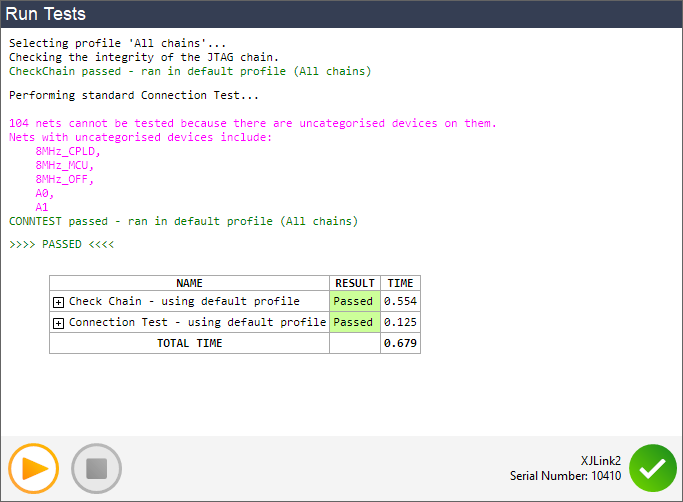
You can see from the output that although the tests pass, a significant part of the circuit is currently untested because uncategorised devices mean not enough is known about its expected behaviour. XJDeveloper can show more details about what is and is not tested, and this will be covered in the next step of the tutorial.
XJTAG v4.3.0