Test Reset Sequence
Some hardware requires a test reset sequence to be applied in order to switch it into a mode where boundary scans will work. Clicking Test Reset Sequence allows you to define a custom test reset sequence for the hardware, in terms of the output JTAG signals TCK, TMS and TDI and any nTRST or PIO pins defined in the pin mapping, as shown below. A test reset sequence may also contain calls to GLOBAL XJEase functions (see Function Scopes), sleep periods, or a TMS reset operation.
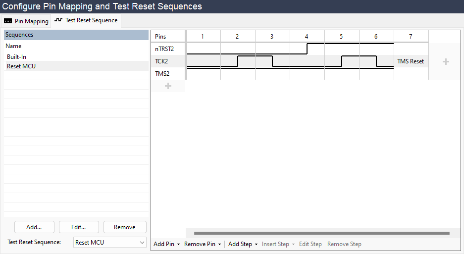
Test Reset Sequence Representation
Test reset sequences are shown in a grid on the right hand side of the screen. Each column of the grid represents a step in the sequence, and each row represents a pin.
If a step sets the value of pins, it is referred to as a waveform step. The pins involved in the sequence can have 3 values:
- Output High – shown as a line at the top of the row
- Output Low – shown as a line at the bottom of the row
- Input (Hi-Z) – shown as a line in the middle of the row
Other kinds of steps that do not set the value of pins are shown as text written in the appropriate column. Sleep steps display the period of the sleep operation in milliseconds. If the text is too long to fit in the column, you can view the full step description by hovering the mouse over the step.
Choosing a Test Reset Sequence
By default, a sequence called Built-In will run as your test reset sequence. This sequence contains just a TMS Reset and cannot be edited or removed. Once you have created another sequence, this first new sequence will then run by default rather than the built-in one. You can change the test reset sequence that will run using the Test Reset Sequence dropdown menu at the bottom of the Sequences list.
If there are any nTRST pins selected in the pin mapping, the Built-In sequence will be replaced by Built-In (nTRST). This is a similar sequence, but includes a Pulse nTRST step at the start.
Adding/Removing Sequences
To add a new test reset sequence, click Add... under the Sequences list, or to view an existing one, click on its name.
Clicking Remove deletes the selected sequence. This will be removed from the pin mapping file associated with the current project next time the project is saved.
Clicking Edit... allows you to rename the selected sequence or change the pins associated with that sequence.
Editing Sequences
Adding/Editing Pins
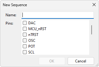
When creating a sequence you first need to add the necessary pins. Pins can be selected from the dialog shown after clicking Add...:
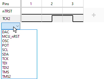
For an existing sequence, you can add pins by hovering the mouse over the + icon in the left-hand column. A dropdown list appears that allows you to select a pin to add:
Alternatively, you can use the Add Pin menu on the bottom toolbar, which also allows you to add pins from external hardware, if that is relevant to your project.
To change a pin, hover over that pin's name in the left-hand column and select a different pin from the dropdown list that appears. If that pin is already in the sequence, the waveform of the two pins will be swapped.
To remove a pin, select Remove from the dropdown list.
Adding/Editing Steps
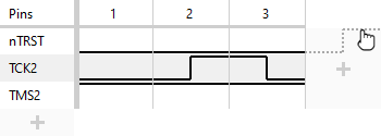
Once pins have been added, you can add waveform steps by clicking the + icon in the rightmost column. You can click in the top, middle or bottom of a cell in this column to choose where the waveform should go for a particular pin:
Existing steps can be edited in a similar fashion:
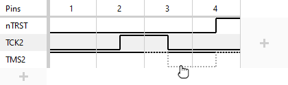
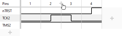
To insert a step into the sequence somewhere other than the end, hover the mouse in between two existing steps and click the + icon that appears in the header row:
To remove a step, right-click anywhere in the step and select Remove Step from the menu. Alternatively, click the step number in the header row to select the step and then either press the Delete key or click Remove Step on the bottom toolbar.
Other kinds of steps can be added by right-clicking instead of left-clicking the + icons for adding or inserting a step. A dropdown menu will appear from which you can select the type of step to add or insert (see Step Types below for a list of possible steps).
To edit an existing non-waveform step (e.g. to change the sleep length or select a different XJEase function), either double-click the step, click the step and select Edit Step on the bottom toolbar, or right-click the step and select Edit Step from the dropdown menu.
To replace an existing step with a different kind of step, right-click the step and select Replace Step With....
Step Types
- Function Call
- Call an XJEase function. The function must have no input parameters and no return parameters, and must be defined with GLOBAL scope (see Function Scopes).
- Pulse nTRST
-
This step will drive any nTRST pins low for one TCK cycle, then set them high and cycle the TCK signal again. Whilst this is happening, any TMS pins will also be held high. In cases where there are multiple TCK pins, they will all be cycled, and if multiple TMS pins are present, they are all held high throughout.
N.B. This step is only available when there is at least one nTRST pin selected in the pin mapping.
- Sequence
- Include and carry out another test reset sequence at this point in the sequence. This allows you to split up your sequence into multiple named parts, to make it clearer to subsequent users what each part does.
- Set Waveform
- Set the value of one or more pins.
- Sleep
- Specify a time to wait without toggling any pins. The sleep is performed after all outstanding hardware accesses have completed.
- TMS Reset
- Perform a TMS reset. Most test reset sequences (but not all) require a TMS Reset as the last operation, in order to reset the JTAG TAP controller circuitry prior to beginning tests.
XJTAG v4.3.0