Running Tests
We will now run some tests on the XJDemo board.
- Make sure your XJDemo board is connected to the XJLink using the 20-way cable provided.
- Click the
 Run button to start the tests.
 - A message will appear asking if the jumpers on your board are in their default locations. Check that your board looks the same as the image displayed and click Yes.
XJRunner will now execute the tests in the order shown on the right side of the screen.
- When prompted, follow the instructions given on-screen by the tests.
- Depending on the project you opened, you may be prompted for a serial number. If so, enter any serial number of up to 7 characters.
- Following the on-screen instructions will:
- Allow the user to confirm that changing the variable resistor changes the measured voltage.
- Test that pressing the pushbutton is correctly detected.
- Allow the user to confirm that the LEDs are working.
When the tests have all finished (and all passed), the test output will print >>>> PASSED <<<< above a summary of the test results, and the icon on the test output pane will change to show a green tick  .
.
To demonstrate the tests failing, we will add a short circuit using one of the jumpers.
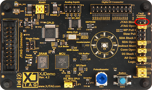
- Use one of the labelled Spare Jumpers underneath the fault creation jumpers FCJ1 to make the connection labelled JTAG Short on FCJ1 - this is marked on the silkscreen on the board as the top set of jumpers, and shorts together nets IO19 and LED9_R.
- With the jumper added, click Run.
- Because you are simulating a fault, keep the jumper on the JTAG Short position but when asked if the jumpers are in the default locations click Yes anyway.
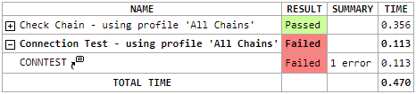
This time, the Connection Test should fail - the display will show >>>> FAILED <<<< and the icon on the test output pane should change to show a red cross  . The test summary will also show that Connection Test has failed.
In order to allow you to visualise this information, each connection test error contains one or more links to XJTAG's Layout Viewer if the board contains ODB++ information and the user has the Layout Viewer privilege.
Single links to nets, devices and pins will also provide a link to the Schematic Viewer if a PDF schematic file has been associated with the board and the user has the Schematic Viewer privilege.
- In the test output, find the Connection Test failure text and click the link Short found between nets in the Connection Test error.
You will see that the Layout Viewer is opened with the nets involved in the short-circuit highlighted to show where they are on the PCB.
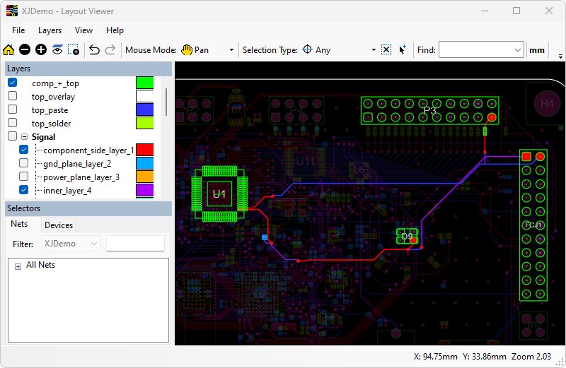
In the displayed image the tracks on the top layer of the PCB are shown in red and the tracks on the bottom layer are shown in blue (XJDemo v4 also has some inner layers). The Layout Viewer will automatically show all the layers that contain tracks for the selected nets. Click here to find out how to change the default layer colours.
Where you have physical access you can check each of these parts of the board to find the short. In this case you can see that the Layout Viewer has highlighted the short we created.
- Back in XJRunner, right-click the link LED9_R in the Connection Test error text.
- Click Show in Schematic Viewer.
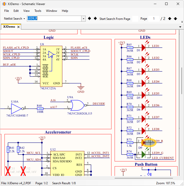
As you can see, Schematic Viewer is opened. The item you selected (D3 or LED9_R) is highlighted in the schematic. If the instance of the item is not the one you want to investigate, the  Previous and
  Next buttons on the toolbar can switch between the instances of a circuit element found in the schematic.
The schematic viewer can provide further insight as to where the problem lies on the board, and which associated components and links are at fault.
Next, we will look at more complex testing.
XJTAG v4.3.0