Adding a manual test device
This step will cover adding adding a test for a manually created device. Here we will simply add and test an LED, although the process is the same for any test device.
- Click the
 Connections screen button under the Setup header, then go to the Manual Devices tab.
 - Click on the
 Add button in the toolbar at the bottom of the screen.
 - Set the Device Name to D1, and the number of pins to 2.
In this case, we categorise this device before defining how it is connected to any JTAG pins - this is because the manual devices tab will fill in bus information from the XJEase file once the device is categorised.
- Click the
 Categorise devices screen button under the Setup header.
 - Uncheck the Only Show Accessible Devices option.
- Categorise D1 as a test device by dragging it from the list of Suggested Diodes onto the Test category in the Assign As panel.
- Click the Browse Library... button on the dialog box that pops up, select the file LED (pin 2).xje from the Switches & Indicators category of the XJEase library and click Select.
- Click OK to close the dialog, clicking No when asked if you want to add a test for this device to the XJRunner test list (we will do it manually later).
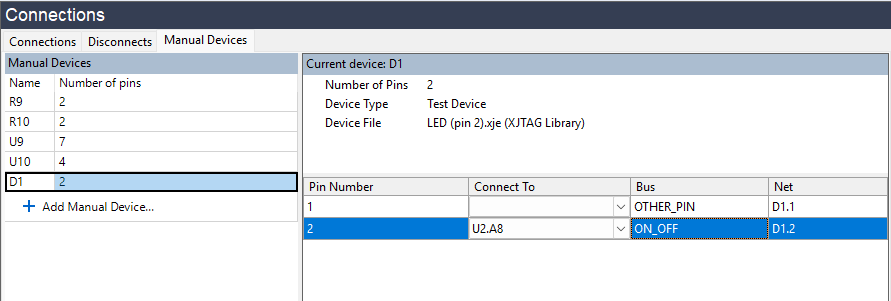
- Return to the manual devices tab on the Connections screen and select D1.
The panels on the right have now been updated, the device type and the device file are displayed and the Bus column shows that pin 2 is on bus ON_OFF. Clicking on the Bus column header will sort the pins by bus - this is particularly useful for large memory devices, where it will group together the address and data busses.
Although the device is categorised as a test device, we cannot test it unless we know how it is connected to the JTAG devices that we can control. The Warnings pane is now displaying a warning that we cannot write to bus ON_OFF. This LED (D1) is connected to pin A8 on U2, so we will add this information now.
- Type U2.A8 in the box next to pin 2 (bus ON_OFF).
- Click the
 Apply button at the bottom of the panel.
The warning is now gone. Note that we do not need to specify how pin 1 is connected, since we do not read from or write to this pin at any point during the test.
This device now behaves in the same way as any other test device on a board with a netlist. It can be added to the test list in exactly the same way:
- Click the
 XJRunner Setup screen button under the Run and Deploy header.
 - Click the Add Group... button at the bottom of the panel.
- Set the test name to LED Test, then expand the Suggested Diodes section and select D1.
- Select the function Test from the bottom panel, and then click the Add Selected Functions button.
- Click OK to close the dialog.
- Click the
 Run Tests screen button under the Run and Deploy header.
 - Click the
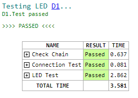
 Run button to run the test, saving when prompted.
 - Follow the on-screen prompt to check and agree that LED D1 is flashing.
Summary
This is the end of the Manually Create Board tutorial. In it you have learned how to setup a simple project without a netlist and how you can add manual devices to resolve errors and extend test coverage. To learn more about using XJDeveloper without a netlist file, see the Manually Create Board Wizard section in XJDeveloper help.
XJTAG v4.3.0