Manually Defining a JTAG Chain
The process of manually defining a JTAG Chain requires the following steps:
- Provide a name for the chain.
- Provide details of where the TDI signal enters the circuit (and optionally where TDO exits).
- Build the chain device-by-device. This involves providing BSDL files for the JTAG devices and categorising any other components or connections in the TDI-TDO signal path.
These steps are described in detail below.
Entering a Chain's Name with its Start and End Points
Go to the Chain Setup section at the top of the JTAG Chain screen and click :
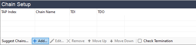
Figure 9: Click to Define a New JTAG Chain
This will open the Add Chain dialog of Figure 10, in which you need to provide a name for the chain and details of where the TDI signal enters the circuit.
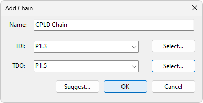
Figure 10: Manually Entering a Chain's Start and End Points
- If your circuit contains multiple chains, it is best practice to provide names that describe the individual chains (e.g. MCU Chain and CPLD Chain). This will help when you come to assign the XJLink2's pins to the different JTAG signals later in the project setup.
To provide details of where the JTAG controller will connect to the TDI and TDO signal in the circuit, either type directly into the box or click the button. Using the button will open the Device and Pin Selector, in which you can pick the connector pin or test point that is used for the JTAG signal.
In the above example, the TDI signal from the XJLink2 enters the circuit on pin 3 of connector P1, and the TDO signal leaves on pin 5.
You can adopt one of three approaches for entering this information:
- Manually enter a connection point for both TDI and TDO.
- Provide only TDI's connection and let XJDeveloper analyse the netlist, BOM, and BSDL files to attempt to trace the signal path and find the associated TDO exit point for you. This is initiated by clicking the dialog box's button after the TDI information has been entered. If that option is used, you will need to provide the BSDL files, as was described above for automatically finding the JTAG chain.
- Just provide TDI and leave TDO undefined at this point.
- Although providing the TDO exit point from the circuit is optional, it is best to enter this now if it is known with certainty because it simplifies the process of adding the final devices to the chain.
Click to enter the data and you will be returned to the JTAG Chain screen. The next step is to build the chain, starting from the TDI connection point as described below.
If the circuit has multiple chains, refer to the section on Allocating the Order of Multiple Chains (TAP Index) above. The XJLink2 supports up to four independent chains, and they will be listed in separate rows at the top of the Chain Setup pane (Figure 9) once their TDI entry points have been defined.
Building the Chain Manually
Once the TDI connection has been provided, a graphical representation of the chain will start to be drawn in the JTAG Chain screen as shown in the example of Figure 11 below. The process for defining the chain is to add the devices to the chain in sequence to build the signal path, starting from the TDI connection.
The box on the left of the pane lists all the devices on the next net of the chain; at this point it shows those that are connected to the TDI input. In the example figure below, the netlist has shown that TDI connects to a resistor, a test point, and an IC. To build the chain, the process is to select whichever device the TDI signal passes through next by double-clicking on its reference. In this example, R11 is a pull-up resistor and U1 is the JTAG device, so U1.15 should be chosen.
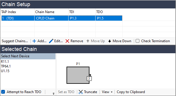
Figure 11: Defining the JTAG Chain Manually
- To view one of the listed devices on the schematic, right-click on the device name and select from the pop-up menu.
Double-clicking a device in the list will open the Edit JTAG Chain dialog box (Figure 12), in which you will need to confirm how XJDeveloper should treat the device.
- If the device has already been categorised, double-clicking it in the Select Next Device box will immediately add it to the chain without needing to use the dialog box to select an action.
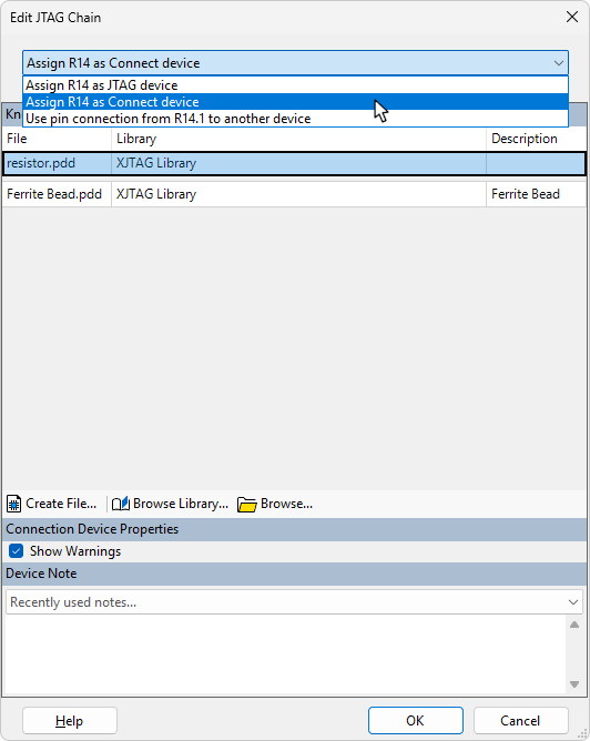
Figure 12: Selecting How to Treat the Next Device in the Chain
One of three possible actions can be taken:
- Categorise the device as a JTAG device.
- Categorise the device as a passive connection device such as a series resistor.
- Define an external connection between this point in the circuit and another point (e.g. when a cable links two test points).
XJDeveloper will suggest a possible action at the top of the dialog but this can be changed if necessary using the dropdown menu (Figure 12 above). Select the required action and click .
The following sections in this user guide describe the steps when the device is:
- a passive such as a series resistor or a link that's fitted to the board
- a JTAG IC
- an external connection (i.e. a link not present in the netlist)
- a non-inverting buffer or a logic gate that functions like one
- Only JTAG devices, passive devices of the Connection type, or external connections can be defined in the JTAG chain. Logic gates in the chain must therefore be treated as passive devices.
Adding a Passive Device
If XJDeveloper detects that the selected device looks like a passive component, it will suggest it should be categorised as a connection, as shown in Figure 13. If it's a 2-pin device, XJDeveloper will attempt to suggest the file to use at the top of the list above the grey bar (1). For a series resistor, this will be resistor.pdd. Any previously used files will be listed below the grey bar (2).
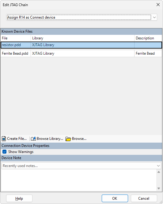
Figure 13: Categorising the Device as a Series Resistor
If no file is suggested or the proposed one is incorrect, use (3) to find a suitable passive device file, or click (4) to create a new one (see the user guide on Categorising Passive Devices for more details of passive device types, and refer to the XJDeveloper Help for a description of how to use the control to create a new file). (5) can be used to locate files not in the library.
Clicking will perform the categorisation, and the graphical representation of the chain will be updated to include the device. The Select Next Device box will now list all the components that could come next in the chain, from which the appropriate device should be selected in the same way.
Adding a JTAG Device
If the selected device is a JTAG-enabled IC, its BSDL file must be provided at this point. Ensure the action shown in the dialog is set to , and the file's location can be entered (Figure 14 below). If you are using the library and the latest file has already been added, click and select the BSDL file for that device. You will be asked if you want to add a copy of the file from the library into your project. It is always recommended that this is done to remove the risk of your project being affected by someone else updating or editing the source BSDL file that's referenced in the library.
If you are not using the library, click instead and navigate to where you saved the latest BSDL file. You will be offered the opportunity to save the BSDL files into the BSDL Library, but this should not be done if the file is stored in your project folder (see Collecting the Required BSDL Files).
If you are using a multi-core device, refer also to Adding a Multi-core JTAG Device below.
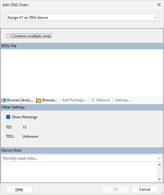
Figure 14: Adding a JTAG Device to the Chain
- It is best practice to ensure you always use the most up-to-date BSDL files for your devices. You should therefore download the latest file for your version of device from the silicon vendor at the start of creating a project. See Collecting the Required BSDL Files.
- If the wrong BSDL file is selected, XJDeveloper will recognise that the chain is not going to connect to the pin that the BSDL file defines as TDI. In that case, the graphical representation of the chain will not be updated, and the device's position in the chain will be marked as Not Found:
- If this happens, either use the button to remove the assignment, or select the device in the list of JTAG devices at the bottom of the dialog and click the button just below it.
- If the JTAG device requires a package file to define non-standard boundary scan cells, XJDeveloper will normally add the required file automatically from its library. In some rare cases, a JTAG device may need an uncommon package file that is not in the XJTAG library. In that situation, you will need to provide the required file – see Loading a Package File for guidance on doing this.
Adding a Multi-Core JTAG Device
If the device to be added is a multi-core device, every core that is in its internal JTAG chain will need to be assigned a BSDL file. It is therefore important when using these devices that all the required BSDL files have been downloaded. Common multicore devices include the Xilinx Zynq® Ultrascale+™, the Intel® Cyclone® V SoC FPGA, and ST STM32 microcontrollers.
Importing BSDL Files
When using a multicore device, follow the steps described above for adding a JTAG device, but place a tick in the checkbox (1):
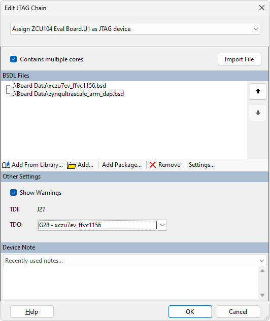
Figure 15: Adding BSDL Files for Multicore Devices
Use the button (2) to import all the required BSDL files. It is important that the order matches the order in which the silicon dies are connected inside the IC package; the top BSDL file must be for the silicon that has its TDI signal bonded to the package's external TDI pin. If necessary, use the up and down arrows (3) to adjust the order.
XJDeveloper must also be told where the TDO signal leaves the device. Each core will have its own set of pin numbers, which might be different to the numbers allocated to the device’s external pins. When telling XJDeveloper which pin is TDO, it is important to provide the number for the external pin rather than an internal one: select the correct output from the TDO: menu (5).
- It is normal for only one of the cores to have connections to the device's physical pins, so the external TDI and TDO connections normally come from the same die.
After clicking the button, the individual cores will be shown in the diagram with a dotted line round them to indicate the complete device:
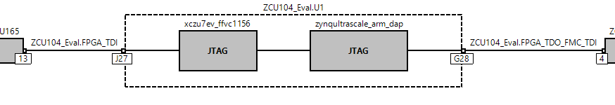
Figure 16: A Multicore Device Shown Graphically
Importing Details of a Previously Used Device
When a multicore device is defined and the project saved, XJDeveloper will create a Multicore Description file. This stores details of which BSDL files are required, their order, and where the TDI and TDO pins are located. If the circuit contains several of the same device, this file removes the need to re-enter the BSDL files each time it is reused: when adding another of these devices to the chain, click the button (with the checkbox ticked) as shown in Figure 17. Navigate to its Multicore Description file (*.mcd) and click . The file can be found in the project folder with the device files.
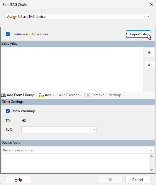
Figure 17: Importing Details of a Previously Defined Multicore Devices
Naming the Core
If the internal logic of a multicore JTAG device is going to be used during a test, it can be important to rename the cores. Some XJEase code refers to the cores by specific names (e.g. the code to initialise a Xilinx UltraScale™ device refers to the cores by name), so the cores must be given matching names when the JTAG device is categorised.
Cores are named by selecting the relevant core and clicking the button – (4) in Figure 15 above. A new name can now be entered into the Core name box:
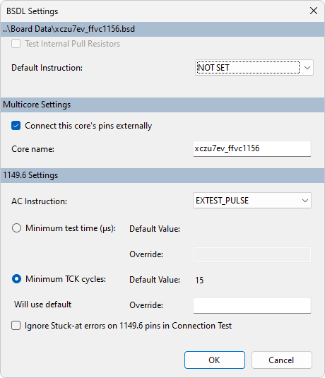
Figure 18: Naming the Core of a Multicore JTAG Device
Adding an External Connection
If the selected device is an external connection such as a cable or wiring in a test fixture that joins different parts of the chain together (i.e. a link that doesn't appear in the netlist), the action that must be selected from the menu is :
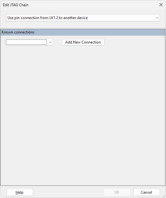
Figure 19: Adding an External Connection to the JTAG Chain
If the link has already been defined in the Connections screen, it will appear in the dropdown menu of Known Connections. In that case, select the required end point and click . If it has not previously been defined, click instead and select the destination device and pin number.
Once added, the connection will be shown in the graphical representation as follows:
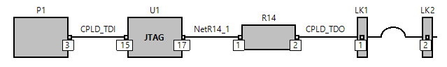
Figure 20: Using an External Connection in a JTAG Chain
Adding a Buffer or Logic Gate to the Chain
Because the JTAG chain must always work correctly, logic gates can only be included in the chain if their functionality is fixed while the chain is in use so that they always allow the JTAG signals to pass through them. The only logic gates allowed in the chain are therefore those that work independently of other circuitry (e.g. do not require clocking) and have an overall functionality that is always the same as a non-inverting buffer (e.g. an AND gate with its other input tied permanently high).
For such a device to be used in the chain, it must be categorised as a passive device with a Connection Type of . To add it to the chain, the action to be selected is therefore .
A suitable passive device file must now be provided. The XJEase library contains files for some standard buffers, and it can therefore be helpful to check the library first if you are using a buffer. If a suitable file is not included, it is easy to create one as described below.
To check for a file in the library, click the button. If a suitable file is present in the JTAG Chain Buffers category, select it as shown in Figure 21.
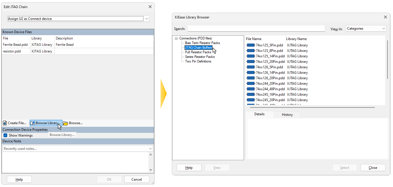
Figure 21: Categorising a Buffer in the JTAG Chain
If the device you're using is not in the library, it will be necessary to create a new passive device file, in which case click in the Edit JTAG Chain dialog box. Figure 22 shows the example of a two-input AND gate; the tied input and the power pins do not appear in the device file when it is used in this way.
For more information on creating passive device files, refer to the User Guide chapter on Categorising Passive Devices.
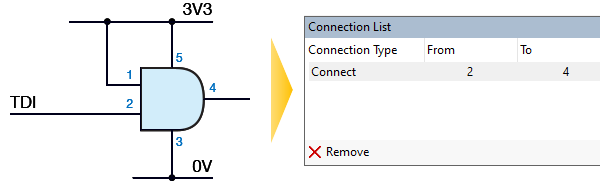
Figure 22: Using an AND Gate in the JTAG Chain
Completing the chain
Continue adding each device in the chain until the final TDO connection is in place.
If the connection point for TDO at the end of the chain was defined during the initial step of creating the chain, XJDeveloper will automatically complete the chain when enough devices have been categorised for it to "see" the path to the final test point or connector (provided the checkbox is ticked at the bottom of the Select Next Device section). The graphical representation will now start and end at the relevant points in the circuit.
A simple example is shown in Figure 23, where TDI enters the circuit on P1 at pin 13 and connects to the only JTAG device in the chain. From that device's TDO output, the signal passes through series resistor R6 before returning to the connector at pin 15.
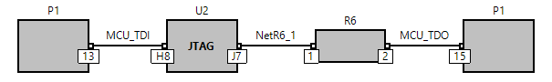
Figure 23: Graphical Representation of a Simple Chain
If TDO has not previously been defined, you will need to tell the software when the end point of the chain has been reached. This is done by right-clicking on the final connector in the Select Next Device section as shown in Figure 24 and choosing from the pop-up menu.
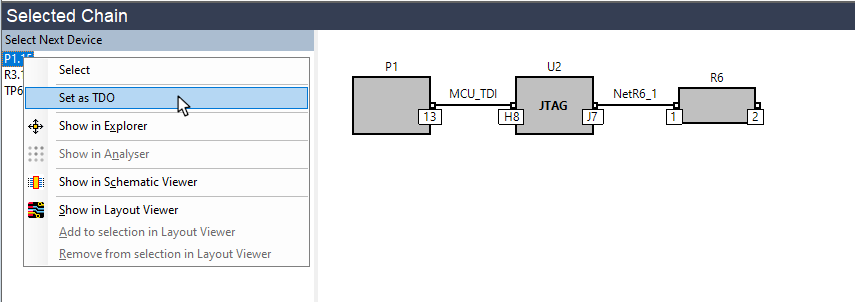
Figure 24: Setting the End Point of the Chain
If the circuit has more than one chain, the whole process above can now be repeated to add the additional chain(s).
Although the TMS and TCK signals are not shown in the diagram of the chain, they are checked to ensure they connect correctly to the JTAG devices in that chain. Any warnings will be displayed in the Warnings tab at the bottom of the screen.
- When you have several JTAG devices in the same chain, their TMS and TCK signals are expected to be connected in parallel. If there are buffers or series resistors in the way, XJDeveloper will generate warnings that these signals are not connected. These warnings can be cleared later by categorising those components as Connect devices in the Categorise Devices screen. For details of creating a suitable passive device file, refer to Adding a Buffer or Logic Gate to the Chain.
Correcting a Mistake
If you make a mistake while defining the JTAG chain, the simplest way to correct it is to use the button at the top of the screen. However, if you need to make amendments to earlier decisions, you may need to remove device categorisations that XJDeveloper performed as part of defining the chain. The steps to do this are described in the following sections.
Truncating a Chain
Consider the example chain shown in Figure 25 below. If a mistake had been made and R11 should not be in the chain (for instance if it was a pull-up resistor rather than a series resistor), the error is corrected by removing the resistor's categorisation. The chain will then be truncated to the point before that resistor, allowing you then to rebuild the chain from that point.
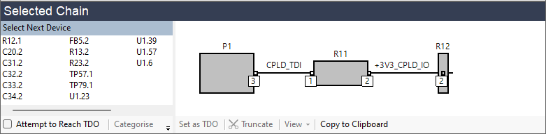
Figure 25: To Remove a Resistor from the Chain, Remove its Categorisation
Removing the categorisation is done on XJDeveloper's Categorise Devices screen: select the device in the Categorised Devices list and click the button.
- If the power and ground nets have all been categorised (and they should always be categorised before defining the chain), XJDeveloper will not allow you to define a chain that goes through a pull-resistor because it recognises the resistor is connected to a power or ground net. Therefore, if you find you have managed to continue the chain through a pull-resistor as in the above example, it also means that the power and/or ground nets are not correctly categorised, and you should check those before continuing.
Correcting a BSDL File Assignment
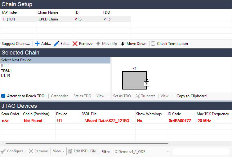
If the wrong BSDL file was assigned, XJDeveloper will probably have identified the error because the netlist's statement of the device's TDI connection is unlikely to match where the BSDL file says TDI should be connected. In that case, the graphical representation of the chain will not have been updated, and the device's position in the chain will be shown as Not found:
Figure 26: An Incorrectly Assigned BSDL File
This mistake can be corrected without leaving the JTAG Chain screen: select the device in the JTAG Devices panel and click the button just below. The correct file can then be allocated by double-clicking the device again in the Select Next Device box and continuing as before.
Correcting an Incorrect External Connection
If the mistake was to insert an external connection in the chain to the wrong point in the circuit, this needs to be edited on XJDeveloper's Connections screen. Find the link in the list of connections and either delete it by selecting it and clicking at the bottom of the Connections screen, or edit it by selecting the connection and clicking at the bottom of the Connections screen. To correct it by editing the link's details, select the correct destination in the To box of the Edit Connection dialog.
You can then return to the JTAG Chain screen and continue as before.
Loading a Package File
If the JTAG device contains any non-standard boundary scan cells, the manufacturer supplies a package file that contains definitions of those cells as well as providing the BSDL file. The XJTAG library contains package files for most non-standard cells and they will be loaded automatically, but if your device requires a package file that is not in the library, you will need to import it after the BSDL file.
When a BSDL file is loaded that requires a package file that isn't in the library, a warning will be displayed in the dialog box as shown in Figure 27. Click the button and locate the required file.
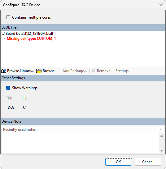
Figure 27: Warning That a Package File is Required
Once the package file has been loaded, it will be shown in a hierarchical structure in the dialog box:
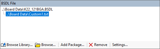
Figure 28: Associated Package Files are Shown in a Hierarchy