Connections and Disconnects
The Connections screen allows you to tell XJTAG about changes to connectivity in your circuit that aren't covered in the netlist. This can be split into three different categories:
- Connections in your circuit, including connections between boards, connections to the XJLink controller and loopback connectors.
- Modifications made to the board since the netlist was created.
- Device behaviour which isn't apparent from the netlist.
Once connections are added, either between multiple boards or between two connectors on the same board, the system will automatically expand the testing to take advantage of this extra coverage, allowing signals to be passed through the connections and for boards to be tested together. It also allows you to connect XJLink pins to nets on the board, further expanding your potential test coverage.
Modifying the board is likely to only happen during prototyping, but XJDeveloper allows you to connect nets together, disconnect specific pins of devices and even add additional components to a circuit in order to represent board modifications.
Some devices will behave in a way that will cause errors to be reported during testing due to the internal connectivity of the device. For instance, a device may have an internal termination resistor connecting two pins together, which can't be represented in the test device model. To get around this, these internal components can be manually added to the circuit representation.
All of these are accomplished through the Connections screen, which consists of 3 tabs, covered individually in the following sections:
- Connections , which allows you to define additional connections to your circuit.
- Disconnects, which allows you to define pins which will not be connected as defined in the netlist.
- Manual Devices, which allows you to define extra devices in the circuit.
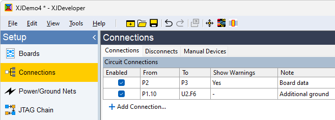
Figure 1: Connections screen and tabs
XJTAG v4.3.0