Categorising Logic Devices
Logic gates will appear on the Categorise Devices screen in the Suggested Devices list. Only those devices that can defined by a truth table should be categorised as Logic; synchronous logic and devices such as latches that hold their state cannot be categorised as Logic (if there's sufficient access to test them, they should be categorised as a test device instead).
There are two main advantages in categorising accessible logic gates as Logic:
- Connection Test automatically includes logic devices in its test.
- If a logic device provides access to a device that will be tested using XJEase, the system will automatically work out how to manipulate the logic's inputs to gain access to the other device.
It is best to categorise logic devices before proceeding to the other devices in the Suggested Devices list because categorised logic can provide access to their pins.
Before categorising a device as Logic, you should check how its pins are connected in the circuit so that you can select the correct model for the device (different pin-outs have different models). If pin numbers are shown on the schematic, they can be viewed by right-clicking on the device and selecting Show in Schematic Viewer. If they are not shown on the schematic, you can check the pin connections by selecting Show in Explorer instead.
- For details of how to use Explorer to check pin allocations, refer to Discovering How a Device's Pins are Connected in the Explorer user guide.
Once you have noted how the device's pins are connected, start the categorisation process. At this point, you may wish to use XJDeveloper's automated Suggest feature as described later. Provided the BOM data includes part numbers, this provides a quick way to categorise devices that have matching library files. Once completed, you will only need to manually categorise devices where matches weren't found.
To continue with manual categorisation, select the device and click the Logic tile. This will open an Assign Device as Logic dialog box similar to Figure 17 below. If you didn't use the Suggest method and a library match exists for the device, it will be shown in the top half of the dialog. A logic part might have multiple pin-out options, in which case more than one model may be offered. To decide which to use, select them one by one and view the pin-out information displayed in the Summary box in the lower half of the dialog. If necessary, you can view more information by clicking Show Details... below that. Alternative footprints for suggestions can be selected from the dropdown menu(s) on the right.
- The different packages listed in a dropdown menu have the same pin-out (i.e., for each row, the packages' pin numbers in that row's menu map to the same signals).
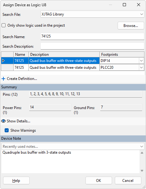
Figure 17: Categorising a Logic Device
- The footprint does not affect how the test will work; what's important is how the pins are numbered. Therefore, if the footprint used on your PCB is not available in the menu, you can safely select another footprint provided it gives you the correct pin allocations.
To see how the model allocates the logic signals to the pins, click  Show Details.... The information will be displayed in a dialog box similar to Figure 18. To view the logic table that will be used, click the
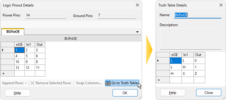
Figure 18: Checking Details of a Logic Device File
Once the correct file has been selected and a footprint chosen, click OK in the Assign Device as Logic dialog to categorise the device.
If a suitable file is not present in the library, a new one should be created. A worked example of how to do this can be found in the tutorial exercise in the XJTAG Help system.
- Assigning logic devices may provide access to other devices in the circuit. After completing the logic assignments, it is therefore important to recheck the previously cleared lists of suggested categorisations for additional devices.
- The additional devices that may need categorisation after logic has been categorised may include ones that the test system cannot control. This can occur when XJDeveloper needs to understand how a logic device's control pins are connected. For example, consider a buffer with an Enable pin that's only connected to a pull resistor: although there is no boundary scan access to that resistor, the software needs to know about it because it is affecting how an accessible logic device behaves. In that situation, a resistor that can't be controlled with boundary scan will be listed and will require categorisation.
XJTAG v4.3.0