Defining and Assigning Power Nets
What is a Power Net?
A net is considered to be a power net if both these points are true:
- It connects to a node that is capable of sourcing or sinking current in excess of a few milliamps without its voltage varying significantly
- Its voltage is at a level that could represent a digital signal in the circuit being tested
Typically, a power net will be associated with a regulator (either analogue or DC switching) or with a power connector on the unit being tested; or be connected to such a net via a device such as a ferrite bead, fuse, or power filter.
Voltage rails derived from a potential divider are not considered power nets because they cannot supply current without their output voltage varying significantly. The output of a termination voltage regulator would not be classified as a power net because it is typically mid-supply and therefore cannot convey a digital level (such nets need to be categorised as termination voltage nets instead).
How to Assign Power, Ground & Termination Voltage Nets in XJDeveloper
Power, ground, and termination voltage nets are assigned in XJDeveloper's Power/Ground Nets screen, which is located within the list of screens under the Setup header:
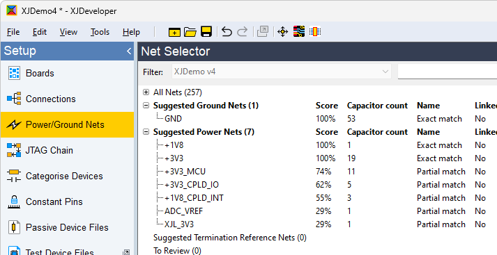
Figure 1: Opening the Power/Ground Nets Screen
The following process is used to tell XJDeveloper which nets are power, ground or termination voltages. This user guide describes these individual steps in detail.
- It is important to spend time early in a project setup to ensure voltage rails are correctly identified. Failure to do so can cause problems later for the reasons described above.
- Review XJDeveloper's proposed net categorisations and assign the obvious power, ground and termination voltage nets to their categories
- Categorise remaining power and ground nets using XJDeveloper's intelligent analysis of the circuit to find the less obvious ones
- Check the categorised nets for any mistakes
XJTAG v4.3.0