Using External Hardware
External hardware can be used in a subchain with or without JTAG devices. This allows you to use a bed-of-nails ICT or a flying probe tester in conjunction with boundary scan to increase test coverage and to control the board before the JTAG chains are started. It also provides a way to control spare XJLink2 PIO pins.
- To be able to use spare pins of the XJLink2 as external hardware, they must have been configured as PIO, and their connections to the UUT must have been defined in the Connections screen.
- To use external hardware other than the XJLink2, it must have been added to a board on the Boards screen.
- If you are using the XJLink2's PIO pins during testing, they can either be controlled by using SET PIO.<pin> in an XJEase function or by setting the system to use them as external hardware. If the pin is only going to be used a few times in the test, it is easiest to use these SET statements. However, if you are using multiple PIO pins for more advanced functionality such as operating an I2C bus, it is simplest to configure the system to use the pins as external hardware. This has the advantage that the system will then automatically decide how to use them to drive and read the required nets, and you can then use standard library files rather than having to write specific code.
To use external hardware with dynamic chains, the process is to create a subchain that includes it and then to add that subchain to a profile.
Adding External Hardware to a Subchain
In the Pin Mapping screen, go to the Advanced Configuration Options tab and click Add... in the Subchains section as described previously in Defining the subchains. In the Add Subchain dialog box that opens, available external hardware will be listed in the bottom half (3) as shown below:
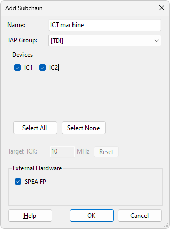
Figure 26: Creating a Subchain with External Hardware
Provide a meaningful name (1) and tick the relevant checkbox(es) to select the required external hardware (3). To use it in conjunction with a JTAG subchain, select the relevant TAP group from the dropdown menu (2) and choose the required subchain from the Devices section. To use the external hardware by itself, select None from the TAP Group menu.
Click OK to save the subchain. It will now appear in the Subchains list.
The subchain can now be included in a profile as described above in Configuring a Profile.
Adding External Hardware to a Profile Without a TAP
When you create a new profile by clicking Add..., subchains consisting only of external hardware will not automatically appear in the Add Profile dialog box (Figure 27). In that situation, you will need to click the Add External Hardware button first to make them visible:
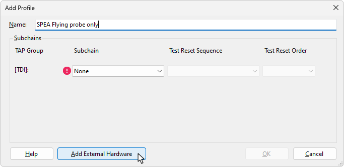
Figure 27: Adding External Hardware that is being used Independently of Subchains
The subchain that includes the external hardware will now be added to the list of possible subchains:
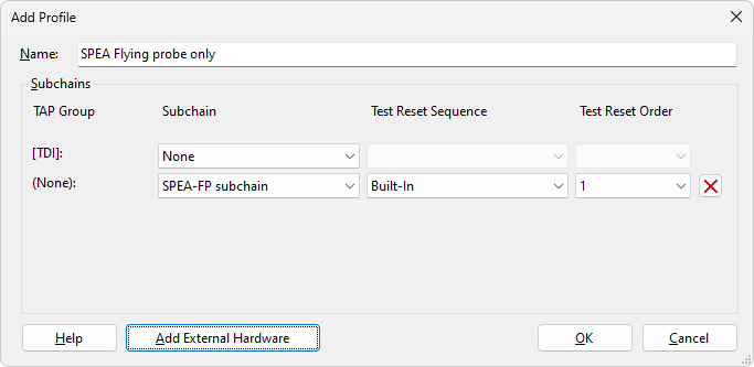
Figure 28: Profile Containing External Hardware Running in Isolation
Click OK to save the profile and it will be added to the list.
Controlling External Hardware in the Test Reset Sequence
In the situation when ICT or spare PIO pins on the XJLink2 are used to set up the board prior to testing (e.g. to control power supplies and/or Reset pins), those outputs can be controlled as part of the Test Reset sequence.
- In addition to the two methods mentioned above to control external hardware pins, it is also possible to control them in the Test Reset sequence. This can be done in two ways: by adding the pin to the waveform and manipulating it directly in the same way as the nTRST pin, or by inserting a call to a function that controls it. The latter requires the XJEase function to use SET statements and to be part of a circuit code file.
- Controlling external hardware pins in the Test Reset sequence can be quicker to implement than the other methods because it does not require the connection to be defined on the Connections screen. However, be aware that setting the pin in the Test Reset sequence will result in it being treated as a Constant pin with a value that cannot be changed during XJEase testing. This is of particular concern if a Flying Probe tester is being used because it will prevent one of the probes from being moved.
Consider the example where an ICT machine is used to drive a test point on the board. The following steps are required:
- Define the connection between the ICT machine and the board (as part of providing the ICT information on the Boards screen).
- Add the ICT pin to the Test Reset sequence for the subchain or create a new sequence for it if one doesn't already exist.
- Set the ICT pin as needed in the Test Reset sequence.
- If required, add a delay in the Test Reset sequence (e.g. to allow voltage rails to settle).
Refer to the earlier section for details of how to use Test Reset sequences with dynamic chains. To add an external hardware pin to a Test Reset sequence, click Add Pin and select External Hardware Pin... from the menu:
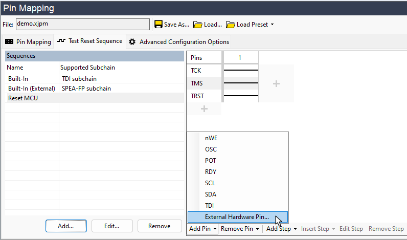
Figure 29: Adding an External Hardware Pin into a Test Reset Sequence
In the dialog box that opens, click Select... to access the Device and Pin Selector as shown below in Figure 30. Expanding All Components will show the external hardware pins. Select the required pin and click OK. Provide it with a descriptive name and click OK in the dialog box to add the pin to the sequence.
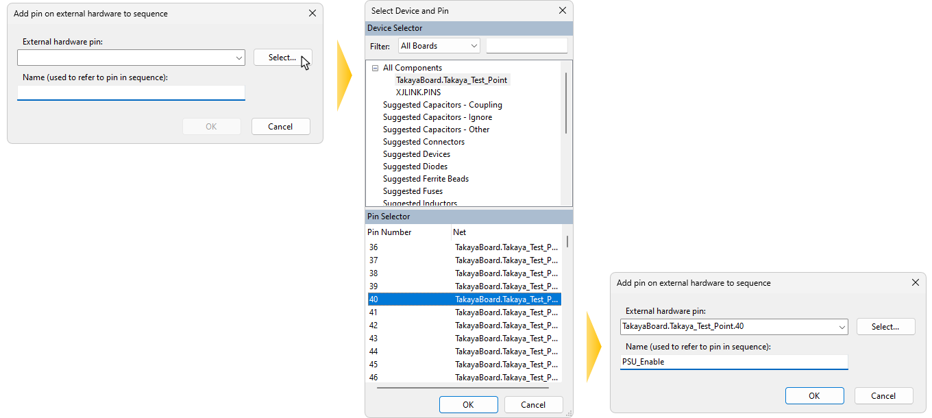
Figure 30: Picking an External Hardware Pin from the Device and Pin Selector
Now that the pin has been added to the sequence, its state can be set. To add a transition on this pin, add a step into the sequence where required and use it to set the pin's logic level. For guidance on adding steps to a Test Reset sequence, refer to JTAG Initialisation and Test Reset Sequences.
If required, a delay can be introduced after setting the PIO by using Insert Step > After Selected Step > Sleep and providing a time in ms. Figure 31 shows an example of a typical Test Reset sequence. An external hardware pin is set high at the start, followed by a 100 ms delay before the JTAG and nTRST signals are used to initialise the JTAG device ready to use it for testing.
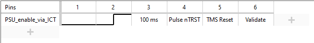
Figure 31: A Test Reset Sequence Using an External Hardware Pin
XJTAG v4.3.0