Linking the two JTAG chains on XJDemo v4
In some situations you may need to configure an XJDeveloper project to have more than one JTAG header connected to a single Test Access Port on your JTAG controller.
This is not a common situation because XJTAG's controllers support multiple JTAG chains - the XJLink-PF20 and all XJLink2 based JTAG controllers support four TAPs and the XJLink-PF40 supports eight. However, if your board has more JTAG chains than your controller supports, then linking them as described in this exercise is an option which will then allow you to create a wiring harness to test your hardware.
Note: This exercise applies only to XJLink2-based JTAG controllers using the XJDemo v4 board. Although the principles apply to other controllers or other hardware, the XJDemo v4 board option to link the JTAG chains does not work with XJLink-PF20 or XJLink-PF40 due to the XJDemo board's pin-out.
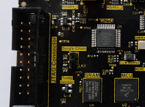
- On the XJDemo Board, use one of the spare jumpers from JP2 to link the pins on the Single Chain header LK1.
The exercise will build on a version of the completed tutorial project with the Pin Mapping, JTAG chains and related devices removed. A copy of this project is installed as a zip file: Demo4NoJTAG.zip.
- Extract the zip file Demo4NoJTAG.zip to a new, empty directory of your choice.
- Navigate into the Board Test directory.
- Open the XJDemo Board.xjd project from the extracted files, using XJDeveloper.
The first thing that you need to do is to add a JTAG chain into this project.
- Click the
 JTAG Chain screen button under the Setup header.
 - Click on the
 Add... button at the bottom of the Chain Setup section.
 - Set the Name of this chain to Full chain.
- Click on the Select... button next to the TDI text box in the Add Chain dialog.
- Open the Suggested Connectors list in the Device Selector section of the Select Device and Pin dialog.
- Click on P1.
- Select pin 3 in the Pin Selector section of the Select Device and Pin dialog.
- Click on OK in the Select Device and Pin dialog and click on OK in the Add Chain dialog, leaving the TDO box empty.
- Click on the
 Save button on the main XJDeveloper toolbar.
XJDeveloper now displays all of the pins attached to the same net as P1.3, the pin defined as being TDI to this JTAG chain, in the Select Next Device section.
There are three other pins connected to the TDI connector pin, P1.3. For this exercise you need to select the TDI of the CPLD, U1.15.
- Double click on U1.15 in the Select Next Device section to select this as the next pin/device in the JTAG chain.
- Click on
 Browse... in the Edit JTAG Chain dialog.
 - Navigate up one level in the directory hierarchy and then into the Board Data directory.
- Select 5M40ZE64.bsd from the files listed and then click on Open.
- Click on the OK button on the Edit JTAG Chain dialog.
You will now be prompted to ask if you want to add the selected BSDL file into the BSDL Library. For this exercise you do not need to add the BSDL files to the library.
- Click the No button on the BSDL Library dialog.
- Click on the Save button on the main XJDeveloper toolbar.
The pin number for TDO is then extracted from the BSDL file and the other pins on the TDO net are displayed in the Select Next Device section. In this instance there is only one option - R14.1, a series termination resistor.
- Double click on R14.1 from the Select Next Device section.
- Click on the OK button at the bottom of the Edit JTAG Chain dialog to accept the default option of categorising R14 as a Connect device using the model resistor.pdd.
The Select Next Device section now shows the pins connected to the net on the other side of R14. There are four other pins on this net, one of these, P1.5, is the connector pin for TDO if the CPLD were being used in a chain on its own.
If you were setting up a linked JTAG chain where devices had separate JTAG headers you would need to select the TDO connector pin, in this case P1.5, from the Select Next Device list. You would then select the option to Use pin connection to another device and create a connection to the TDI pin on the JTAG header for the next device.
For this exercise you are going to tell XJDeveloper that the chain now goes through LK1 (the jumper you fitted at the start of this exercise).
- Double click on LK1.1 from the Select Next Device section.
XJDeveloper has not been able to identify which device model should be used; however because LK1 is a two pin device it has preselected Assign LK1 as Connect device from the drop down list.
As the file used to categorise a jumper has not been used in the project before you will now need to tell XJDeveloper which file it should use from the installed library.
- Click on the Browse Library... button.
- Select Two Pin Definitions under Connections (PDD files) in the XJEase Library Browser.
- Select link (1-2).pdd from the list of models in the panel on the right side of the dialog.
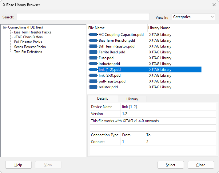
- Click on the Select button in the XJEase Library Browser.
- Click on the OK button at the bottom of the Edit JTAG Chain dialog to categorise LK1 as a Connect device using the model link (1-2).pdd.
The Select Next Device section now shows the pins connected to the net on the other side of LK1. The TDI pin for the next JTAG device is in this list, U2.H8.
- Double click on U2.H8 in the Select Next Device section to select this as the next pin/device in the JTAG chain.
- Click on Browse... in the Edit JTAG Chain dialog.
- Select K22_121BGA.BSDL from the files listed and then click on Open.
- Click on the OK button on the Edit JTAG Chain dialog.
- Click the No button on the BSDL Library dialog.
- Click on the Save button on the main XJDeveloper toolbar.
There is another series termination resistor, R6, that now needs to be categorised as a Connect Device to allow the chain to be routed back to the JTAG connector, P1.
- Double click on R6.1 from the Select Next Device section.
- Click on the OK button at the bottom of the Edit JTAG Chain dialog to accept the suggestion to categorise this resistor as a passive device using the model resistor.pdd.
- Select P1.15 and click on the Set as TDO button.
- Click on the Save button on the main XJDeveloper toolbar.
This completes the JTAG chain with both of the devices from the XJDemo board. The full chain is now displayed, as shown below.

Having completed the JTAG chains there will be multiple errors in the project. These are due to the pin mapping being the default demo board pin mapping, which is not correct for this project with linked JTAG chains.
The last step to allow the project to run with this new single chain configuration is modify the pin mapping.
We have linked the two chains on the board by connecting TDO of one chain to TDI of the next, but each of the original chains has its own TCK and TMS signals which now need to operate synchronously with the other chain. Rather than connecting them via a wiring harness, setting both TCK nets to be the TCK signal on the XJLink results in the same signal being driven out on both, and likewise for TMS.
- Click the
 Pin Mapping screen button under the Run and Deploy header.
 - Under Supported XJLink Types remove the XJLink-PF20 and XJLink-PF40 types which are not usable in this tutorial, by selecting each one in turn and clicking Remove XJLink Type beneath the list of XJLink types.
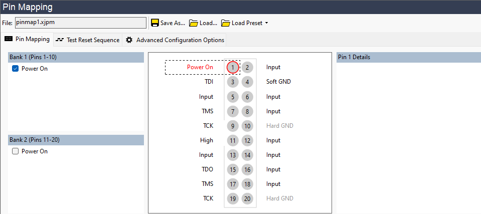
- Select the TDO pin in the pin mapping diagram and set it to be of Type Input in the Details panel to the right.
- Select the TDI2 pin in the pin mapping diagram and set it to be of Type Input in the Details panel to the right.
- Find the TDO2 pin in the pin mapping diagram, right-click on it and select TDO from the Set TDO sub-menu, in order to assign it as the new single chain output.
- Find the TMS2 pin in the pin mapping diagram and change it to be TMS by right-clicking on it and selecting TMS from the Set TMS sub-menu.
- Find the TCK2 pin in the pin mapping diagram and change it to be TCK by right-clicking on it and selecting TCK from the Set TCK sub-menu.
- Similarly, find the nTRST2 pin in the pin mapping diagram and change it to be nTRST by right-clicking on it and selecting nTRST from the Set nTRST sub-menu.
- Check that the Power On checkbox in Bank 1 (Pins 1-10) is set to enable power to the XJDemo board.
- Click on the Save button on the main XJDeveloper toolbar.
This should clear the error, and the tests defined in the project should now be able to be executed again.
N.B. Because the models used to categorise the non-JTAG devices are device-centric none of the rest of the project needs to be altered.
- Remember to remove the Single Chain shorting link on LK1 before doing any further tutorial exercises.
See Also
XJTAG v4.3.0